


UV lamp Box circuit
#UV lamp
#ultraviolet light
#transistor
#heatsink
#12-volt
#PCB making
#NPN power transistor
#4-watt tubes
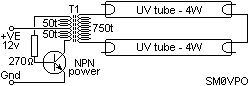
Description: There is no PCB since there are no components to mount on one. The object was to create a source of ultraviolet light as fast as possible. The UV tubes I bought from a lighting shop for use with handheld battery lamps using 4-watt tubes. The tubes are white in color and deliver light from about 390nm to 450nm, which is ideal for making PCBs. The transistor is almost any NPN power transistor and heatsink that can deliver 15 watts comfortably. The resistor is selected for the highest value that will cause the tubes to strike when cold with 12-volts applied to the circuit. Use TIP31, 2N3055, almost anything. Just do not forget the heatsink. The transformer T1 is a 4cm diameter ferrite "Pot Core" wound with 50 + 50 turns of about 22 SWG enamelled wire for the primary and 750 turns of about 38 SWG enamelled wire. Wind the secondary in two layers separated with a layer of waxed paper. If you get any arcing inside the transformer then it does not work for very long! Finally, keep your fingers away from the tube terminals; they sting a bit! There is not enough power to do you any injury, but you will certainly know about it if you touch them. Also, be very careful if you use the "black light" UV tubes sold for forged banknote detectors. I believe they work okay, but I have not tried them in the past 10 years. UV light from "black light" tubes can be dangerous to the eyes. If you become blinded, then it's your own fault; don't look at me!
The circuit described is a straightforward ultraviolet (UV) light source designed for applications such as PCB exposure. The absence of a printed circuit board (PCB) indicates a minimalist approach, focusing on rapid assembly and functionality. The use of 4-watt UV tubes, which emit light in the 390nm to 450nm range, is appropriate for PCB development, as this wavelength is effective for photoresist exposure.
The circuit employs an NPN power transistor, which is crucial for driving the UV tubes. Suitable choices include the TIP31 or 2N3055, both of which are capable of handling the necessary power output while dissipating heat through an adequate heatsink. The resistor in the circuit must be selected carefully; it should be of the highest value that still allows the tubes to ignite when a 12-volt supply is applied, ensuring reliable operation during startup.
The transformer (T1) is a ferrite pot core with specific winding requirements. The primary winding consists of 50 turns of 22 SWG enamelled wire, and the secondary winding is significantly larger, with 750 turns of 38 SWG enamelled wire. The winding process is critical; the secondary should be wound in two layers, separated by waxed paper, to prevent arcing and ensure the longevity of the transformer. Any arcing can lead to rapid failure of the transformer, so careful attention to the winding technique is essential.
Safety precautions are emphasized, particularly regarding the handling of the UV tubes. While the voltage levels involved may not be lethal, they can produce a noticeable sting upon contact. Additionally, caution is advised when using "black light" UV tubes, as they can pose risks to eyesight. Proper protective measures, such as UV-blocking eyewear, should be employed to mitigate these risks.There is no PCB since there are no components to mount on one. the object was to create a source of Ultr Violet light as fast as possible. The UV tubes I bought from a lighting shop for use with handheld battery lamps using 4-watt tubes. the tubes are white in colour and deliver light from about 390nm to 450nm which is ideal for making PCBs. The transistor is almost any NPN power transistor and heatsink that can deliver 15 watts comfortably.
The resistor is selected for the highest value that will cause the tubes to strike when cold with 12-volts applied to the circuit. Use TIP31, 2N3055, almost anything. just do not forget the heatsink. The transformer T1 is a 4cm Dia. ferrite "Pot Core" wound with 50 + 50 turns of about 22 SWG enamelled wire for the primary and 750 turns of about 38 SWG enamelled wire. Wind the secondary in two layers separated with a layer of waxed paper. If you get any arcing inside the transformer then it does not work for very long! Finally, keep your fingers away from the tube terminals, they sting a bit! There is not enough power to do you any injury but you will certainly know about it if you touch them.
Also be very carefull if you use the "black light" UV tubes sold for forged banknote detectors. I believe they work Ok ut I have not tried them in the past 10 years. UV light from "black light" tubes can be dangerous to the eyes. If you become blinded then it's your own fault, don't look at me!
The circuit described is a straightforward ultraviolet (UV) light source designed for applications such as PCB exposure. The absence of a printed circuit board (PCB) indicates a minimalist approach, focusing on rapid assembly and functionality. The use of 4-watt UV tubes, which emit light in the 390nm to 450nm range, is appropriate for PCB development, as this wavelength is effective for photoresist exposure.
The circuit employs an NPN power transistor, which is crucial for driving the UV tubes. Suitable choices include the TIP31 or 2N3055, both of which are capable of handling the necessary power output while dissipating heat through an adequate heatsink. The resistor in the circuit must be selected carefully; it should be of the highest value that still allows the tubes to ignite when a 12-volt supply is applied, ensuring reliable operation during startup.
The transformer (T1) is a ferrite pot core with specific winding requirements. The primary winding consists of 50 turns of 22 SWG enamelled wire, and the secondary winding is significantly larger, with 750 turns of 38 SWG enamelled wire. The winding process is critical; the secondary should be wound in two layers, separated by waxed paper, to prevent arcing and ensure the longevity of the transformer. Any arcing can lead to rapid failure of the transformer, so careful attention to the winding technique is essential.
Safety precautions are emphasized, particularly regarding the handling of the UV tubes. While the voltage levels involved may not be lethal, they can produce a noticeable sting upon contact. Additionally, caution is advised when using "black light" UV tubes, as they can pose risks to eyesight. Proper protective measures, such as UV-blocking eyewear, should be employed to mitigate these risks.There is no PCB since there are no components to mount on one. the object was to create a source of Ultr Violet light as fast as possible. The UV tubes I bought from a lighting shop for use with handheld battery lamps using 4-watt tubes. the tubes are white in colour and deliver light from about 390nm to 450nm which is ideal for making PCBs. The transistor is almost any NPN power transistor and heatsink that can deliver 15 watts comfortably.
The resistor is selected for the highest value that will cause the tubes to strike when cold with 12-volts applied to the circuit. Use TIP31, 2N3055, almost anything. just do not forget the heatsink. The transformer T1 is a 4cm Dia. ferrite "Pot Core" wound with 50 + 50 turns of about 22 SWG enamelled wire for the primary and 750 turns of about 38 SWG enamelled wire. Wind the secondary in two layers separated with a layer of waxed paper. If you get any arcing inside the transformer then it does not work for very long! Finally, keep your fingers away from the tube terminals, they sting a bit! There is not enough power to do you any injury but you will certainly know about it if you touch them.
Also be very carefull if you use the "black light" UV tubes sold for forged banknote detectors. I believe they work Ok ut I have not tried them in the past 10 years. UV light from "black light" tubes can be dangerous to the eyes. If you become blinded then it's your own fault, don't look at me!
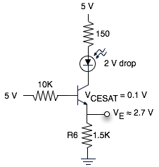
Transistor Circuit Analysis
The schematic represents a relatively simple transistor circuit. Analyzing such schematics evokes memories of college days spent studying electrical engineering. However, the complexity of the schematic can be daunting after a long time away from the subject. To refresh knowledge,...

TRANSISTORIZED THYRATRON RING COUNTER
Each bistable circuit comprises two oppositely-symmetrical germanium transistors, two diodes, and four resistors. An additional transistor, Q, facilitates the transition of the conducting state to the next position when actuated by a transfer pulse. The absence of capacitors allows for...
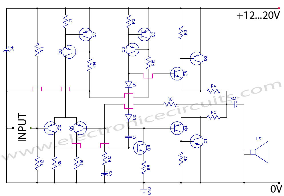
transistor power amplifier circuit diagram
Discrete Class AB Transistor Audio Power Amplifier Circuit Diagram. This is a Class AB transistor power amplifier. It is a simple amplifier to...
A Class AB transistor audio power amplifier is designed to provide high-quality amplification for audio signals while maintaining...
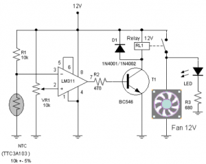
Transistors Function in the fan speed Control
The circuit schematic diagram of a fan speed control system that activates only when necessary. When the transistor heats up, the fan will automatically turn on.
The fan speed control circuit operates based on the temperature of the transistor, utilizing a...
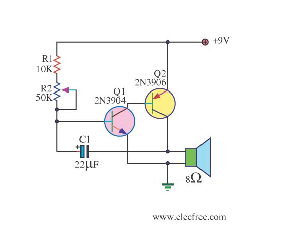
Simple Metronome using transistor
This circuit is a simple metronome model designed for ease of use. It employs transistors as key components, specifically configured as an astable multivibrator, to produce a beeping sound. The tone can be adjusted using a variable resistor (VR1). A...
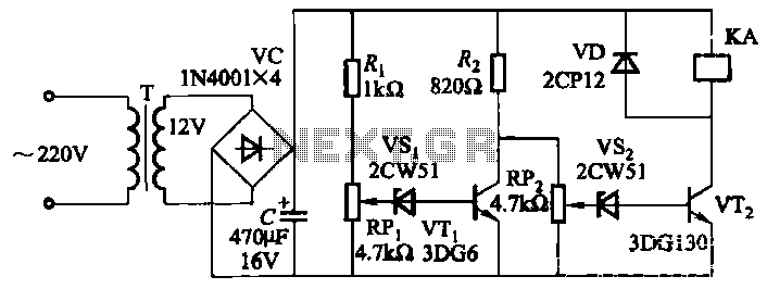
Mains undervoltage overvoltage protection circuit
The circuit employs a transistor control mechanism. When the grid voltage is within the normal range, relay KA is activated, supplying power to the load. If the grid voltage falls below the minimum allowable threshold (adjustable via potentiometer RPz) or...
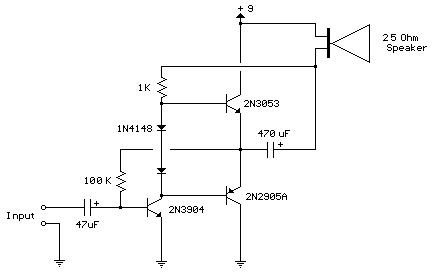
80 milliwatt Improved 3 Transistor Audio Amp
This circuit is similar to the previous one but utilizes positive feedback to increase the amplitude to the speaker. It was adapted from a small 5-transistor radio that employs a 25-ohm speaker. In the prior circuit, the load resistor for...
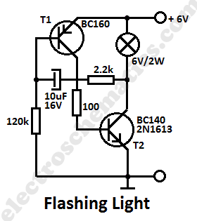
Flashing Light Circuit with Transistors
This simple flashing light circuit operates at 6 volts and 0.5A, exhibiting low current consumption when the light bulb is turned off. The frequency of the flashing is predetermined.
The circuit consists of a power supply, typically a battery or a...

Single Transistor Audio Mixer Circuit
This single transistor audio mixer is utilized in an amplifier circuit design featuring a base-driven transistor, with its emitter being current-controlled.
This audio mixer circuit employs a single transistor to facilitate the mixing of audio signals. The transistor operates in a...