


Variable-strobe-light
#strobe-light
#flashtube
#voltage-doubler
#transformer
#high-voltage
#capacitor
#trigger-circuit
#lighting
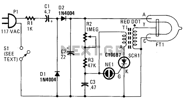
Description: In this strobe light, two circuits are required: one circuit charges a capacitor to create a 320 V DC potential between the cathode and anode of the flashtube, while the other circuit generates bursts of approximately 4000 V to trigger the flashtube into conduction. The voltage doubler operates by adding two equal voltages in series, effectively doubling the voltage. The 4000 V necessary for triggering the flashtube is supplied by transformer T1, a voltage step-up transformer that produces 4000 V across its secondary coil when current flows through its primary coil.
Further, a silicon-controlled rectifier (SCR1) regulates the current flow in the primary coil of T1. When SCR1 is activated, current rapidly flows through the primary coil, generating 4000 Vac spikes across the secondary coil. For SCR1 to conduct, it requires a negative voltage on the cathode, a positive voltage on the anode, and a positive voltage on the gate. The components R2, R3, C3, and NE1 are responsible for providing the necessary positive gate voltage to trigger SCR1. The combination of potentiometer R2, resistor R3, and capacitor C3 forms an RC timing circuit that controls the charging time of C3 by adjusting the resistance in the circuit. Once the voltage on C3 reaches the firing voltage of the neon bulb, it prompts NE1 to conduct, applying a positive voltage from C3 to the gate of SCR1. Consequently, SCR1 turns on, allowing C3 to discharge through SCR1 and the primary coil of T1. The resulting 4000 V generated across the secondary coil of T1 ignites the xenon tube, producing a bright flash. This entire cycle then repeats, with C3 recharging, NE1 firing to short out SCR1, and T1 generating the necessary 4000 V to trigger the xenon flashtube.
The strobe light circuit consists of a careful arrangement of components to ensure reliable operation and precise timing. The RC timing circuit, comprising R2, R3, and C3, is crucial for determining the flash duration and frequency. Adjusting the potentiometer R2 alters the charging time of C3, thereby influencing the interval between flashes. The use of a neon bulb (NE1) as a trigger mechanism ensures that the gate of SCR1 receives the appropriate voltage at the right moment, allowing for efficient energy transfer and minimizing wear on the components through controlled discharge cycles.
Overall, this design exemplifies the integration of high-voltage components and timing circuits to achieve the desired performance in a strobe light application, ensuring that the xenon flashtube is triggered accurately and consistently for effective illumination.In this strobe-light, two circuits are needed; one circuit charges a capacitor placing 320 V de between the cathode and anode of the flashtube. The other circuit provides bursts of approximately 4000 V to trigger the flashtube into conduction. The voltage-doubler works by summing two equal voltages in series, which results in a doubling of the voltage.
The 4000 V needed to trigger the flashtube is provided by transformer Tl-a voltage step-up transformer that develops 4000 V across its secondary coil when current flows in the primary coil. Silicon-controlled rectifier SCRl controls the current flow in the primary coil of Tl. When SCRl conducts, current flows suddenly in the primary coil and 4000 Vac spikes appear across the secondary coil. For conduction, SCRl needs a negative and positive voltage on the cathode and anode, respectively, and a positive voltage on the~gate.
It is the function of components R2, R3, C3, and NEl to provide that positive gate voltage and turn on SCRl. Potentiometer R2, resistor R3, and capacitor C3 form an rc timing circuit. Control of charging time of C3 is accomplished by varying that resistance in the circuit. When the voltage on C3 reaches the firing voltage of the neon bulb, it causes NEl to conduct, thus placing a positive voltage, from C3, on the gate of SCRl.
The SCR now turns on and C3 discharges through SCRl and the primary coil of Tl. The 4000 V that is developed across the secondary coil of Tl fires the xenon tube, causing a bright flash. The whole process then repeats itself with C3 charging up, NEl firing to short out SCRl, and T1 developing 4000 V to trigger the xenon flashtube.
Further, a silicon-controlled rectifier (SCR1) regulates the current flow in the primary coil of T1. When SCR1 is activated, current rapidly flows through the primary coil, generating 4000 Vac spikes across the secondary coil. For SCR1 to conduct, it requires a negative voltage on the cathode, a positive voltage on the anode, and a positive voltage on the gate. The components R2, R3, C3, and NE1 are responsible for providing the necessary positive gate voltage to trigger SCR1. The combination of potentiometer R2, resistor R3, and capacitor C3 forms an RC timing circuit that controls the charging time of C3 by adjusting the resistance in the circuit. Once the voltage on C3 reaches the firing voltage of the neon bulb, it prompts NE1 to conduct, applying a positive voltage from C3 to the gate of SCR1. Consequently, SCR1 turns on, allowing C3 to discharge through SCR1 and the primary coil of T1. The resulting 4000 V generated across the secondary coil of T1 ignites the xenon tube, producing a bright flash. This entire cycle then repeats, with C3 recharging, NE1 firing to short out SCR1, and T1 generating the necessary 4000 V to trigger the xenon flashtube.
The strobe light circuit consists of a careful arrangement of components to ensure reliable operation and precise timing. The RC timing circuit, comprising R2, R3, and C3, is crucial for determining the flash duration and frequency. Adjusting the potentiometer R2 alters the charging time of C3, thereby influencing the interval between flashes. The use of a neon bulb (NE1) as a trigger mechanism ensures that the gate of SCR1 receives the appropriate voltage at the right moment, allowing for efficient energy transfer and minimizing wear on the components through controlled discharge cycles.
Overall, this design exemplifies the integration of high-voltage components and timing circuits to achieve the desired performance in a strobe light application, ensuring that the xenon flashtube is triggered accurately and consistently for effective illumination.In this strobe-light, two circuits are needed; one circuit charges a capacitor placing 320 V de between the cathode and anode of the flashtube. The other circuit provides bursts of approximately 4000 V to trigger the flashtube into conduction. The voltage-doubler works by summing two equal voltages in series, which results in a doubling of the voltage.
The 4000 V needed to trigger the flashtube is provided by transformer Tl-a voltage step-up transformer that develops 4000 V across its secondary coil when current flows in the primary coil. Silicon-controlled rectifier SCRl controls the current flow in the primary coil of Tl. When SCRl conducts, current flows suddenly in the primary coil and 4000 Vac spikes appear across the secondary coil. For conduction, SCRl needs a negative and positive voltage on the cathode and anode, respectively, and a positive voltage on the~gate.
It is the function of components R2, R3, C3, and NEl to provide that positive gate voltage and turn on SCRl. Potentiometer R2, resistor R3, and capacitor C3 form an rc timing circuit. Control of charging time of C3 is accomplished by varying that resistance in the circuit. When the voltage on C3 reaches the firing voltage of the neon bulb, it causes NEl to conduct, thus placing a positive voltage, from C3, on the gate of SCRl.
The SCR now turns on and C3 discharges through SCRl and the primary coil of Tl. The 4000 V that is developed across the secondary coil of Tl fires the xenon tube, causing a bright flash. The whole process then repeats itself with C3 charging up, NEl firing to short out SCRl, and T1 developing 4000 V to trigger the xenon flashtube.
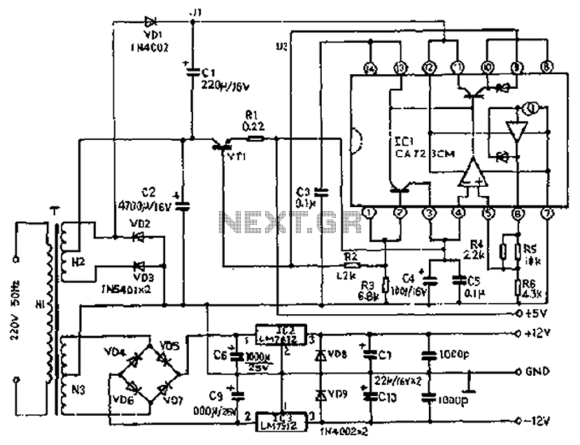
Precision tandem type power supply circuit diagram
The circuit depicted features a secondary N3 center tap transformer (T) with a common point connecting diodes VD2 and VD3 to positive electrodes, along with capacitors C2, C6, C7, and negative electrodes connected to capacitors C9 and C10. Additional components...
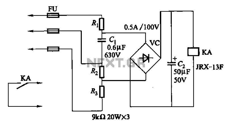
The second phase alarm circuit
A capacitor C1 and resistors R1-R3 form a negative sequence voltage filtration device. The resistors and capacitors must meet the following requirements: R1, R2, R3 = 5.5/C1 (KN). The relationship between the resistance and capacitance values is arbitrary. Capacitor selection...

adj pwr
The design incorporates a universal capacitor mounting and spacing feature, enabling compatibility with various capacitor types. It includes a mounting pattern suitable for TO-200 or TO-218/247 packages, specifically for the pass transistor and the transistor utilized in the current limit...
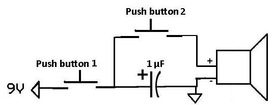
Apply a Pulse to a Speaker Using a Capacitor
This project demonstrates how a capacitor can supply a pulse signal to a speaker. A capacitor is charged and then discharges its voltage to a speaker, which acts as a transducer that converts electrical signals into sound. The result is...
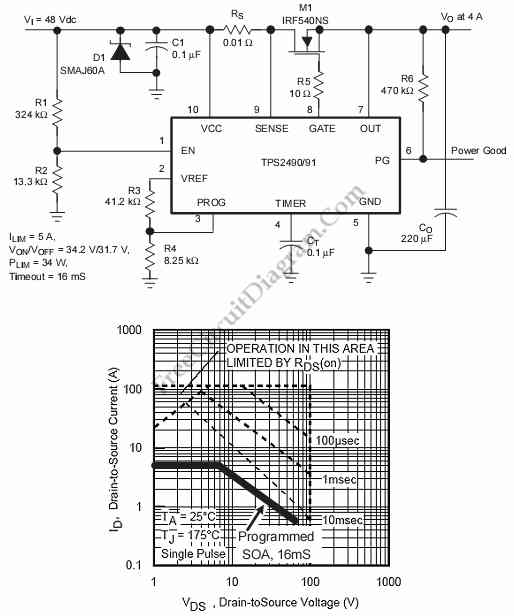
Positive High-Voltage Hot Swap Controller with Power Limiter
This is a positive high-voltage hot swap controller circuit with a power limiter. This circuit utilizes the TPS2491 or TPS2490, as both of them have specific features.
The positive high-voltage hot swap controller circuit is designed to safely connect and disconnect...
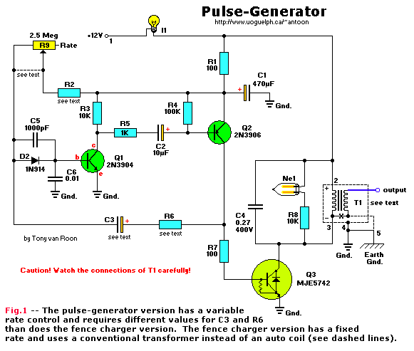
High-Voltage Pulse Generator
If you have ever wanted a high-voltage generator to create impressive lightning effects, conduct Kirlian photography experiments, or experiment with neon lights, this project is ideal. It describes a laboratory pulse generator utilizing an auto-ignition coil, capable of delivering a...
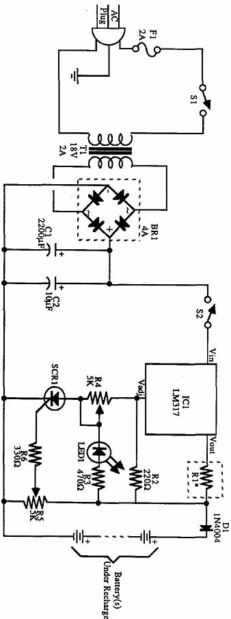
Build an Experimenters Power Supply
The incoming AC is routed to the primary terminals of a 12.6-volt transformer. The hot side of the AC is connected through a fuse and a single-pole single-throw (SPST) toggle switch. When the switch is in the OFF position, the...
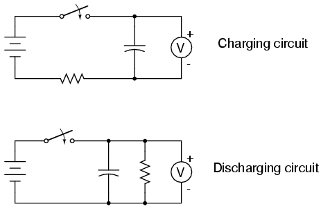
Capacitor charging and discharging
Large-value capacitors are necessary for this experiment to generate time constants slow enough to be monitored with a voltmeter and stopwatch. It is important to note that most large capacitors are of the "electrolytic" type, which are sensitive to polarity....
HIGHWAY ALERT SIGNAL LAMP
The lighting system of a motor vehicle comprises lighting and signaling devices mounted or integrated at the front, sides, rear, and sometimes the top of the vehicle. This system's purpose is to provide illumination for the driver to operate the...