


Whistle Light Switch
#UM3763
#piezo-ceramic buzzer
#whistle detection
#light switch
#sound activated
#home automation
#IC
#frequency detection
#electronic switch
#audio trigger
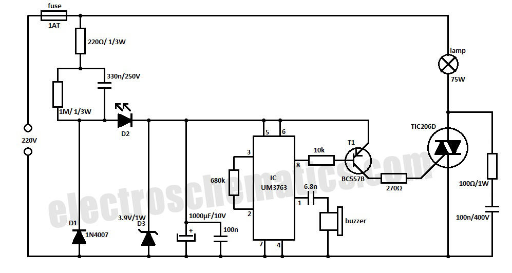
Description: This whistle light switch allows for the control of lighting installations. The primary component of this circuit is the UM3763 integrated circuit, manufactured by UMC. A piezo-ceramic buzzer serves as a microphone, detecting sound frequencies between 1.2 kHz and 1.8 kHz. When such a frequency is detected, the output of the IC switches to a HIGH state, resulting in the light turning ON if it was previously OFF, or turning OFF if it was ON. The UM3763 controls a triac (T1) for light regulation. The circuit is powered directly from the main power supply, with diodes D1 and D2 functioning as rectifiers, while D3 limits the voltage to 3.9 V. An LED (D2) is incorporated as an indicator of the operating or idle state.
The whistle light switch circuit is designed to provide a user-friendly method for controlling lighting through sound activation. The UM3763 IC is central to the operation, as it is engineered to respond specifically to a narrow band of sound frequencies. This selective frequency response ensures that the circuit is activated only by intentional sounds, reducing the likelihood of false triggering from background noise.
The piezo-ceramic buzzer is employed not only as a sound emitter but also as a sensor, capitalizing on its ability to convert acoustic energy into electrical signals. Upon detecting the specified frequency range, the UM3763 outputs a HIGH signal, effectively enabling the triac (T1). The triac acts as a switch, allowing the mains voltage to flow to the connected lighting fixture, thus controlling the illumination state.
Power supply considerations are critical for the circuit's reliability. The circuit is powered directly from the mains, which necessitates the inclusion of rectifier diodes (D1 and D2) to convert alternating current (AC) to direct current (DC). The rectification process ensures that the voltage supplied to the UM3763 and other components is stable and within operational limits. The use of D3 as a voltage limiter is essential to protect the IC from over-voltage conditions, ensuring its longevity and consistent performance.
The LED indicator (D2) provides visual feedback regarding the circuit's status, illuminating when the circuit is active and extinguishing when idle. This feature enhances user interaction by clearly signaling whether the lighting system is engaged or not.
Overall, this whistle light switch circuit combines efficient sound detection, reliable power management, and clear user feedback, making it a practical solution for automated lighting control in various applications.With this whistle light switch you can turn on and off the lighting installation. The main part of this circuit is the UM3763 IC, produced by UMC. The piezo-ceramic buzzer is used here as a microphone and when it receives a tone frequency between 1. 2 kHz and 1. 8 kHz, the IC`s output will go HIGH. This means that the light will go ON if it was OFF, or go OFF it was ON. For light control the UM3763 triggers a triac through T1. The supply voltage is taken directly from the main power supply. D1 and D2 diodes are used as rectifiers, and D3 limits the voltage at 3. 9 V. D2 LED is used as an indicator of operating or idle state.
The whistle light switch circuit is designed to provide a user-friendly method for controlling lighting through sound activation. The UM3763 IC is central to the operation, as it is engineered to respond specifically to a narrow band of sound frequencies. This selective frequency response ensures that the circuit is activated only by intentional sounds, reducing the likelihood of false triggering from background noise.
The piezo-ceramic buzzer is employed not only as a sound emitter but also as a sensor, capitalizing on its ability to convert acoustic energy into electrical signals. Upon detecting the specified frequency range, the UM3763 outputs a HIGH signal, effectively enabling the triac (T1). The triac acts as a switch, allowing the mains voltage to flow to the connected lighting fixture, thus controlling the illumination state.
Power supply considerations are critical for the circuit's reliability. The circuit is powered directly from the mains, which necessitates the inclusion of rectifier diodes (D1 and D2) to convert alternating current (AC) to direct current (DC). The rectification process ensures that the voltage supplied to the UM3763 and other components is stable and within operational limits. The use of D3 as a voltage limiter is essential to protect the IC from over-voltage conditions, ensuring its longevity and consistent performance.
The LED indicator (D2) provides visual feedback regarding the circuit's status, illuminating when the circuit is active and extinguishing when idle. This feature enhances user interaction by clearly signaling whether the lighting system is engaged or not.
Overall, this whistle light switch circuit combines efficient sound detection, reliable power management, and clear user feedback, making it a practical solution for automated lighting control in various applications.With this whistle light switch you can turn on and off the lighting installation. The main part of this circuit is the UM3763 IC, produced by UMC. The piezo-ceramic buzzer is used here as a microphone and when it receives a tone frequency between 1. 2 kHz and 1. 8 kHz, the IC`s output will go HIGH. This means that the light will go ON if it was OFF, or go OFF it was ON. For light control the UM3763 triggers a triac through T1. The supply voltage is taken directly from the main power supply. D1 and D2 diodes are used as rectifiers, and D3 limits the voltage at 3. 9 V. D2 LED is used as an indicator of operating or idle state.
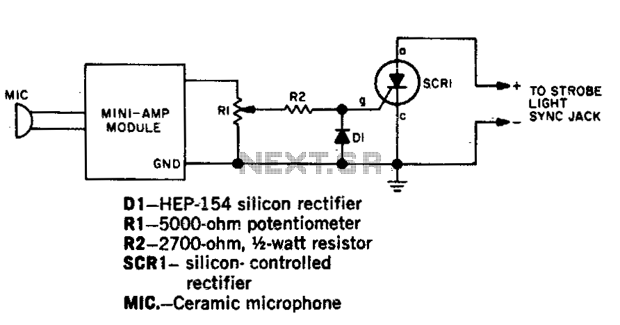
Sound activated strobe trip
Capture strobe-flash images at the precise moment a pin punctures a balloon, a hammer shatters a lamp bulb, or a bullet exits a firearm. Utilize a transistor amplifier rated at 1 watt or less, which must include an output transformer....
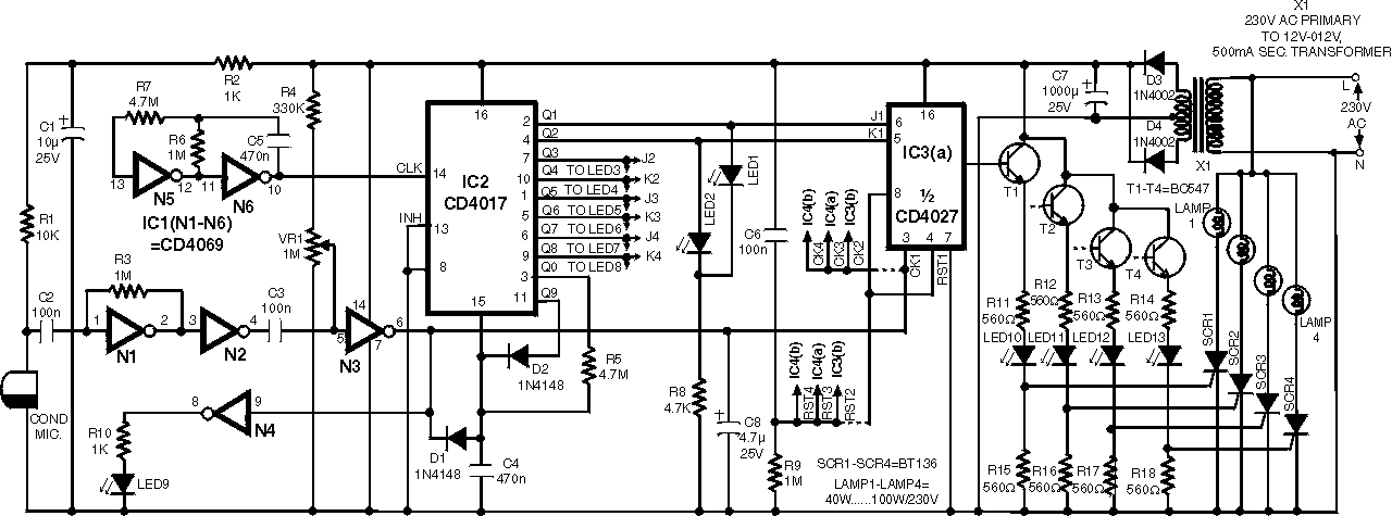
Sound activated switch circuit
An infra-red or wireless remote control has the disadvantage that the small, handy, remote transmitter is often misplaced. The sound operated switch has the advantage that the transmitter is always with you. This project offers a way to control up...
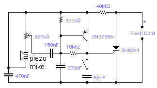
Sound Trigered Camera flash
If you wish to take a picture of a fleeting event which generates a sound, you can do it with this sound activated trigger. It does not require any power supply: it feeds on the high voltage available on the...
Sound activated relay
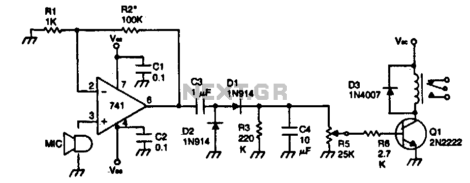
The device remains dormant (in an off condition) until a sound activates it. The input stage consists of a 741 operational amplifier configured as a non-inverting audio amplifier with a gain of approximately 100. To increase the gain, the value...
build yourself this simple sound activated alarm
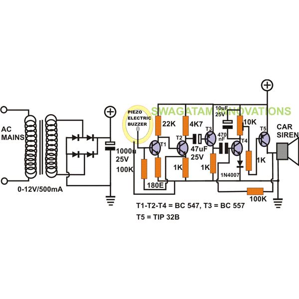
The project "DIY: Build a Sound Activated Switch" presented here is straightforward to construct and can be very useful in protecting a specific area from potential theft or intrusion. Learn how to build a simple sound-activated alarm here on Bright...
home automation Installation
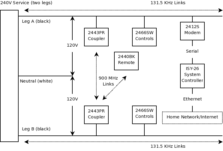
First and foremost, if one is not skilled with tools and electrical systems, it is advisable to hire a qualified electrician rather than attempting to undertake this task independently. The electrician should review this page for specific cautions and advice....

Quartz Controlled Bedroom Light Switch
This is a simple automatic light switch circuit designed for bedrooms. After construction, connect the input terminals of this circuit in parallel to the internal buzzer terminals of a quartz alarm clock. When the clock alarm is activated, the circuit...
Digital-frequency-window
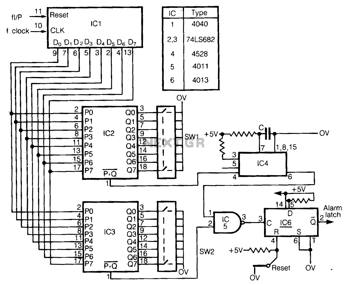
This circuit detects frequency variations that exceed preset limits. IC1 functions as a binary counter connected to the clock frequency (FcLK). The outputs from IC1 are compared with preset values set by IC2 and IC3. The input signal, which must...
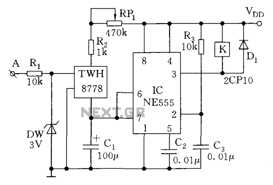
Optionally extended charging pulse count switch circuit diagram
The count switching circuit consists of an electronic switch and a pulse delay circuit for control.
The count switching circuit is designed to manage the switching of signals in a controlled manner. The electronic switch serves as the primary component for...