


Xenon Flash with LM311
#xenon flash
#LM311
#voltage comparator
#relay
#high power unit
#transmitter trim
#receiver
#PIC16F84
#230V
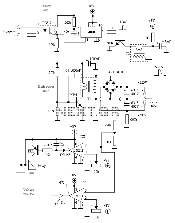
Description: The reason why I built this unit is because I need to trim my transmitters for the best performance. I have noticed that I can't be at the receiver position and the transmitter position at the same time. So, what I have invented is a XFI. I connect the receiver to a decoder (PIC16F84) which will trigger the XFI. I can now trim the transmitter for best performance by sending a signal which will control the XFI. When power is switched on, the power over the Xenon tube is zero. The voltage comparator LM311 (IC1) monitors the X-tube voltage and controls a relay for the "high power unit." As long as the X-tube voltage is lower than 230V, the LM311 will charge C2 and the relay will pull the contacts together so the "high power unit" gets power.
The other LM311 (IC2) will light D1 when the voltage over the X-tube has reached 420V. With P2, you can set this level. Start to build the "high power unit" and test it. If it won't oscillate, try to flip the connection on the transformer. You can also play with the value of C1 (200pF to 10nF). It will vary the charging voltage and the charging time. When you get that working, connect the bank-capacitor. Remember one capacitor will be charged to +250V and the other to -250V, totaling 500V. BE CAREFUL!!
The "trigger unit" shouldn't be any problem to build. If you have high power over the X-tube and you got a trigger pulse from T2 and still can get the X-tube to flash, you should try to flip the connection on transformer T2.
The "trigger unit" consists of a monostable CMOS 4098. When it is triggered, it will deliver a 12ms pulse into T2. T2 is a normal 220V to 6V transformer turned in the opposite direction. The output from this unit will be about 2-3 kV. This pulse will trigger the Xenon tube and it will flash. The high power unit is an oscillator. T1 is a 220V to 12V transformer turned in the opposite direction. It up-transforms the voltage and a diode bridge (or some diodes) rectifies the voltage to a DC which charges the 400V capacitors over the X-tube. When the voltage reaches 230V, the output from LM311 (IC1) will go high. With P1, you can set this level. C2 will now start to discharge for 16 seconds more, the relay will still hold the contacts together. After that 16 seconds, the relay will open the contacts. The power supply to the "high power unit" will be disconnected from +8V. The X-tube voltage is now about 520V and will start to discharge slowly. When the voltage drops under 230V, the LM311 (IC1) will start the procedure again.
The described circuit is a high-voltage trigger and control system for a Xenon flash tube, designed to optimize transmitter performance. The system utilizes two LM311 voltage comparators to monitor and control the voltage across the Xenon tube, ensuring it operates within specified limits. The first LM311 (IC1) is responsible for managing the charging of a capacitor (C2) and controlling a relay that powers the high-power unit. The second LM311 (IC2) activates an indicator LED (D1) when the voltage reaches a predefined threshold of 420V, adjustable via potentiometer P2.
The high-power unit operates as an oscillator, utilizing a transformer (T1) to step up the voltage from 220V to a higher level, which is then rectified by a diode bridge to charge the capacitors connected to the Xenon tube. The system is designed to handle voltages up to 520V, with safety measures in place to manage the discharge of the capacitors, which are charged to +250V and -250V, ensuring a total potential difference of 500V.
The trigger unit, based on a CMOS 4098 monostable multivibrator, generates a short pulse (12ms) to initiate the firing of the Xenon tube. This pulse is delivered to a transformer (T2), which is configured to produce a high-voltage output of 2-3 kV for triggering the flash tube. The design allows for flexibility in tuning the system, including adjusting the capacitor values (C1), which affects the charging time and voltage levels.
Overall, this circuit is a sophisticated solution for remotely tuning transmitters while ensuring safety and reliability in high-voltage operations. Proper precautions must be taken when working with high voltages to prevent accidents or equipment damage.The reason why I built this unit is becasue I need to trim my transmitters for the best performance, I have noticed that I can't be at the receiver position and the transmitter position at the same time! So, what I have invented is a XFI. I connect the receiver to a decoder (PIC16F84) wich will trigg the XFI. I can now trim the transmitter for best performance by sending a signal wich will controll the XFI.When power is switched on, the power over the Xenon tube is zero.
The voltage comparator LM311 (IC1) monitor the X-tube voltage and control a relay for the "high power unit". As long as the X-tube voltage is lover than 230V the LM311 will charge C2 and the relay will pull the contacts together so the "high power unit" get power.
The other LM311 (IC2) will light D1 when the voltage over the X-tube has reached 420V. With P2 you can set this level. Start to build the "high power unit" and test it. If it won't oscillate try to flip the conection on the transformer. You can also play with the value of C1 (200pF to 10nF). It will vary the charging voltage and the charging-time. When you get that working, conect the bank-capacitor. Remember one capacitor will be charged to +250V and the other to - 250V, totally 500V. BE CAREFUL!! The "trigger unit" shoulden't be any problem to build, If you have high power over the X-tube an you got a trigger-puls from T2 and still can get the X-tube to flash, you should try to flip the connection on transformator T2. The "trigger unit" consist of a monostabil vippa CMOS 4098. When it is trigged it will deliver a 12mS puls into T2. T2 is a normal 220V to 6V transformer turned into opposite direction. The output from this unit will be about 2-3 kV. This puls will trigger the Xenon tube and it will flash. The high power unit is an oscillator. T1 is a 220V to 12 V transformer turned into opposite direction. It upptransform the voltage and a diod bridge (or some diods) rectify the voltage to a DC wich charge the 400V capacitors over the X-tube.
When the voltage reach 230 V the output from LM311 (IC1) will go high. With P1 you can set this level. C2 will now start to discharge for 16 sec more, the relay will still hold the contacts together. After that 16 seconds, the relay will open the contacts. The power supply to the "high power unit" will be disconected from + 8 Volt. The X-tube voltage is now about 520V and will start to discharge slow. When the voltage drops under 230V the LM311 (IC1) will start the procedure again.
The other LM311 (IC2) will light D1 when the voltage over the X-tube has reached 420V. With P2, you can set this level. Start to build the "high power unit" and test it. If it won't oscillate, try to flip the connection on the transformer. You can also play with the value of C1 (200pF to 10nF). It will vary the charging voltage and the charging time. When you get that working, connect the bank-capacitor. Remember one capacitor will be charged to +250V and the other to -250V, totaling 500V. BE CAREFUL!!
The "trigger unit" shouldn't be any problem to build. If you have high power over the X-tube and you got a trigger pulse from T2 and still can get the X-tube to flash, you should try to flip the connection on transformer T2.
The "trigger unit" consists of a monostable CMOS 4098. When it is triggered, it will deliver a 12ms pulse into T2. T2 is a normal 220V to 6V transformer turned in the opposite direction. The output from this unit will be about 2-3 kV. This pulse will trigger the Xenon tube and it will flash. The high power unit is an oscillator. T1 is a 220V to 12V transformer turned in the opposite direction. It up-transforms the voltage and a diode bridge (or some diodes) rectifies the voltage to a DC which charges the 400V capacitors over the X-tube. When the voltage reaches 230V, the output from LM311 (IC1) will go high. With P1, you can set this level. C2 will now start to discharge for 16 seconds more, the relay will still hold the contacts together. After that 16 seconds, the relay will open the contacts. The power supply to the "high power unit" will be disconnected from +8V. The X-tube voltage is now about 520V and will start to discharge slowly. When the voltage drops under 230V, the LM311 (IC1) will start the procedure again.
The described circuit is a high-voltage trigger and control system for a Xenon flash tube, designed to optimize transmitter performance. The system utilizes two LM311 voltage comparators to monitor and control the voltage across the Xenon tube, ensuring it operates within specified limits. The first LM311 (IC1) is responsible for managing the charging of a capacitor (C2) and controlling a relay that powers the high-power unit. The second LM311 (IC2) activates an indicator LED (D1) when the voltage reaches a predefined threshold of 420V, adjustable via potentiometer P2.
The high-power unit operates as an oscillator, utilizing a transformer (T1) to step up the voltage from 220V to a higher level, which is then rectified by a diode bridge to charge the capacitors connected to the Xenon tube. The system is designed to handle voltages up to 520V, with safety measures in place to manage the discharge of the capacitors, which are charged to +250V and -250V, ensuring a total potential difference of 500V.
The trigger unit, based on a CMOS 4098 monostable multivibrator, generates a short pulse (12ms) to initiate the firing of the Xenon tube. This pulse is delivered to a transformer (T2), which is configured to produce a high-voltage output of 2-3 kV for triggering the flash tube. The design allows for flexibility in tuning the system, including adjusting the capacitor values (C1), which affects the charging time and voltage levels.
Overall, this circuit is a sophisticated solution for remotely tuning transmitters while ensuring safety and reliability in high-voltage operations. Proper precautions must be taken when working with high voltages to prevent accidents or equipment damage.The reason why I built this unit is becasue I need to trim my transmitters for the best performance, I have noticed that I can't be at the receiver position and the transmitter position at the same time! So, what I have invented is a XFI. I connect the receiver to a decoder (PIC16F84) wich will trigg the XFI. I can now trim the transmitter for best performance by sending a signal wich will controll the XFI.When power is switched on, the power over the Xenon tube is zero.
The voltage comparator LM311 (IC1) monitor the X-tube voltage and control a relay for the "high power unit". As long as the X-tube voltage is lover than 230V the LM311 will charge C2 and the relay will pull the contacts together so the "high power unit" get power.
The other LM311 (IC2) will light D1 when the voltage over the X-tube has reached 420V. With P2 you can set this level. Start to build the "high power unit" and test it. If it won't oscillate try to flip the conection on the transformer. You can also play with the value of C1 (200pF to 10nF). It will vary the charging voltage and the charging-time. When you get that working, conect the bank-capacitor. Remember one capacitor will be charged to +250V and the other to - 250V, totally 500V. BE CAREFUL!! The "trigger unit" shoulden't be any problem to build, If you have high power over the X-tube an you got a trigger-puls from T2 and still can get the X-tube to flash, you should try to flip the connection on transformator T2. The "trigger unit" consist of a monostabil vippa CMOS 4098. When it is trigged it will deliver a 12mS puls into T2. T2 is a normal 220V to 6V transformer turned into opposite direction. The output from this unit will be about 2-3 kV. This puls will trigger the Xenon tube and it will flash. The high power unit is an oscillator. T1 is a 220V to 12 V transformer turned into opposite direction. It upptransform the voltage and a diod bridge (or some diods) rectify the voltage to a DC wich charge the 400V capacitors over the X-tube.
When the voltage reach 230 V the output from LM311 (IC1) will go high. With P1 you can set this level. C2 will now start to discharge for 16 sec more, the relay will still hold the contacts together. After that 16 seconds, the relay will open the contacts. The power supply to the "high power unit" will be disconected from + 8 Volt. The X-tube voltage is now about 520V and will start to discharge slow. When the voltage drops under 230V the LM311 (IC1) will start the procedure again.
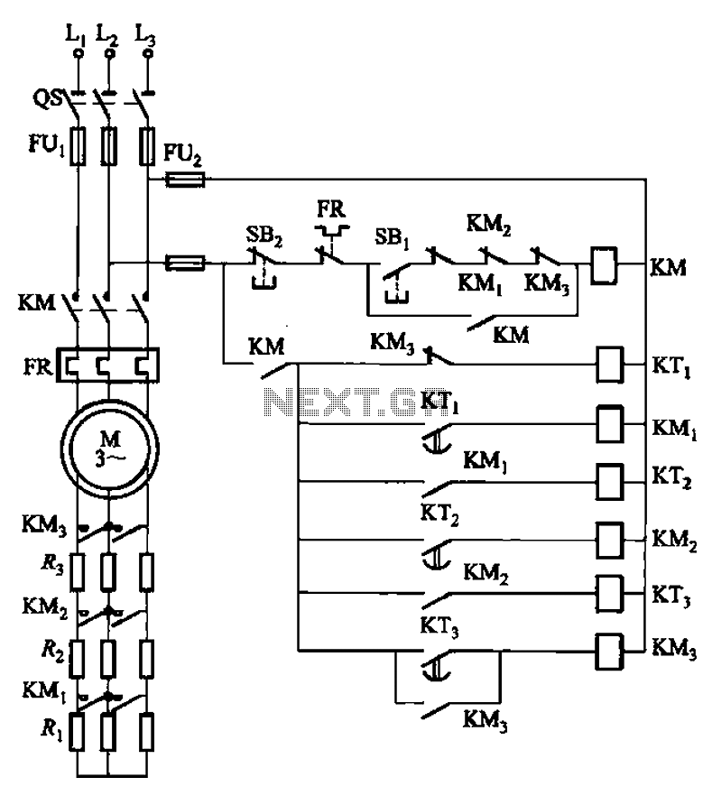
Time relay three-start circuit
The circuit depicted in Figure 3-159 employs complementary operation three times along with three relay contacts. This is followed by the automatic elimination of the rotor circuit resistance levels, ultimately reducing the rotor winding variable resistor to zero (fully shorted),...
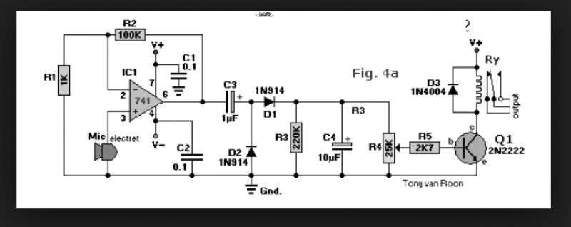
sound activated relay
A circuit that enables control of a relay in response to sound from a non-amplified sound source, such as a computer, CD player, or a Digital Sound Recorder board. This circuit accepts audio input from any non-amplified sound source, and...
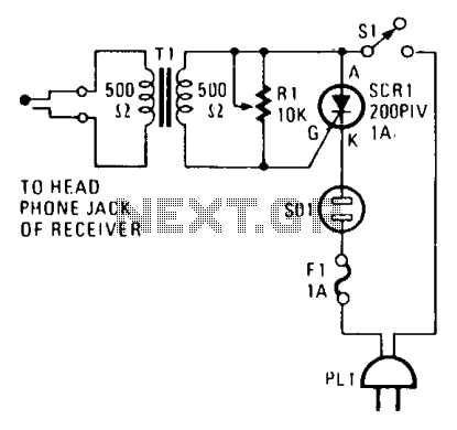
Receiver monitor
The alarm connects to the earphone jack on a receiver. When a signal, typically sent to the headphones, is detected and applied to the gate of SCR1, it conducts, activating the alarm connected to SOI. The signaling device can be...
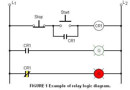
Know About The Relay Logic
The relay logic circuit creates an electrical schematic diagram for controlling input and output devices. Components include resistors, capacitors, and others.
The relay logic circuit operates by utilizing electromechanical relays to control various input and output devices in a systematic manner....
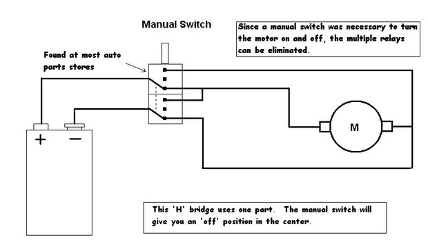
what relay should i use parallel port
Control a toy car. The toy car is operated via a wired controller, rather than being radio-controlled. The intention is to utilize relays to control the toy through a parallel port. There are various types and models of relays, and...
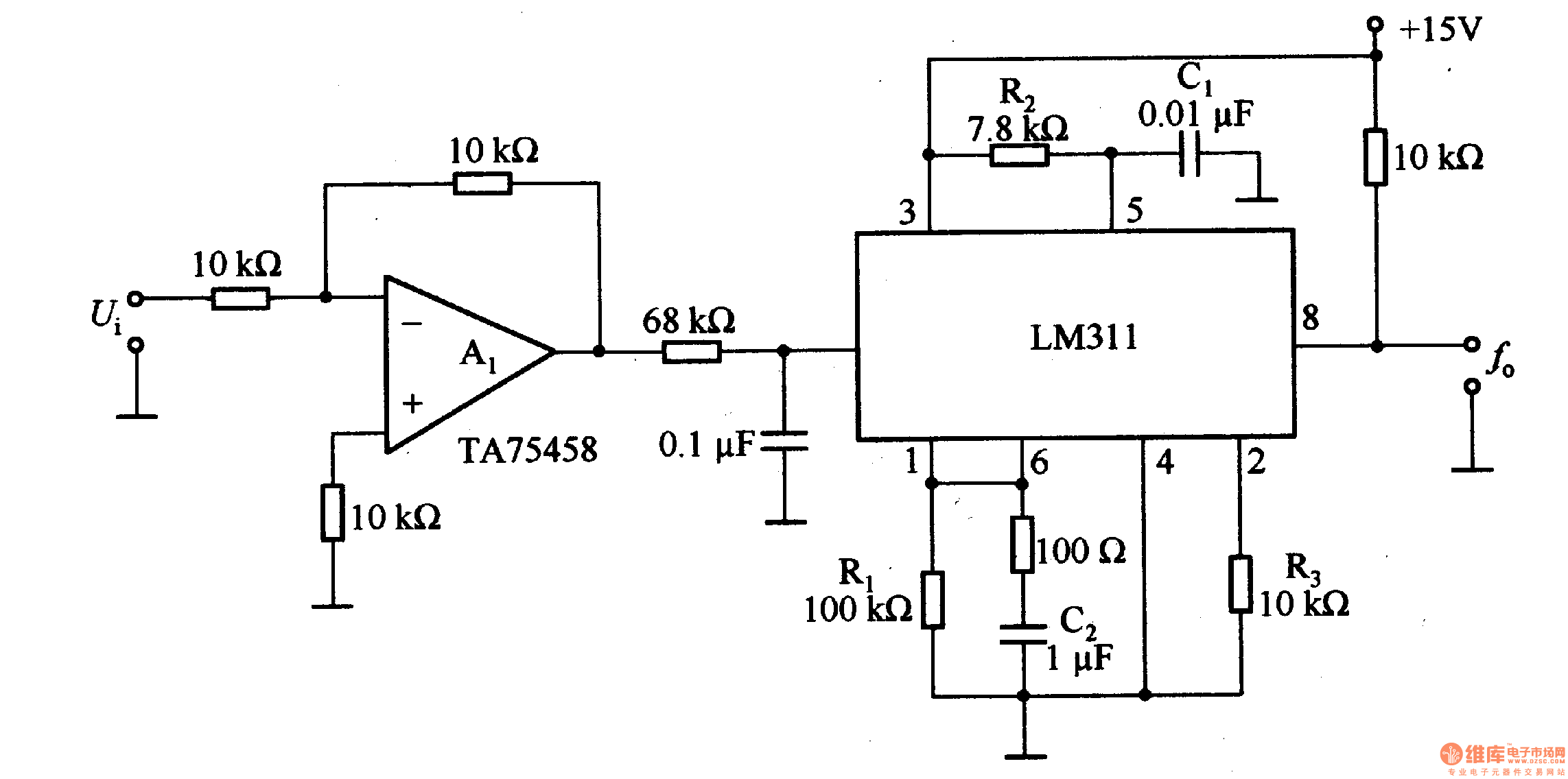
frequency conversion circuit composed of LM311
The LM311 is an integrated circuit that functions as a reference voltage generator, comparator, amplifier, and discharge circuit. It is designed for ease of use. In the circuit, the output frequency f0 is...
The LM311 is a versatile integrated circuit that...
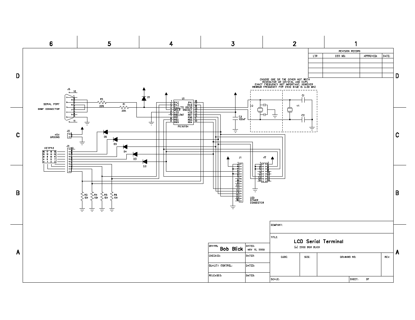
LCD Serial Terminal
This project is a self-contained serial terminal using a PIC16F84 microcontroller chip, an inexpensive LCD character display, a keypad, and very little else. It is full-duplex, meaning keypresses cause RS-232 output, and RS-232 input makes characters appear on the LCD....
jk electrical lighting sound systems
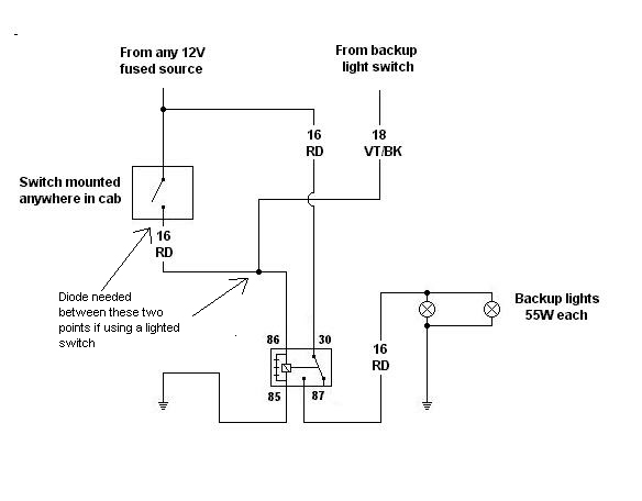
Utilizing a relay allows for a reduction in the length of thick wires that need to be routed, particularly through the firewall and beneath the dashboard. This approach also minimizes the necessity for a larger switch. However, when integrating with...
Voltage Comparator Circuits
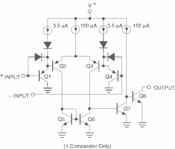
This page provides basic information about voltage comparator integrated circuits and is to act as reference material for other circuits. The circuits shown are based on the LM339 Quad Voltage Comparator chip or the LM393 Dual Voltage Comparator chip. These...