


100Hz-1MHz a circuit diagram of the phase meter
#phase meter
#frequency range
#sine wave
#square wave
#bode curve
#accuracy
#signal processing
#measurement
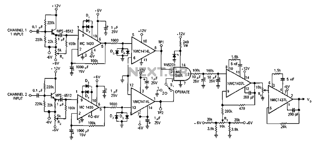
Description: A circuit designed to operate within a frequency range with an accuracy greater than 2% for generating Bode plots. It converts two sine waves into a square wave, taking into account the overlap relative to the total input wave cycle. The direct input phase difference between the wave trains reaches 180 degrees.
The described circuit is intended for precise frequency analysis and is particularly useful in control systems and signal processing applications. It utilizes two sine wave inputs, which are typically generated by function generators or oscillators. The conversion of these sine waves into a square wave is achieved through a comparator or a Schmitt trigger, which ensures that the output transitions cleanly between high and low states.
The overlap of the input sine waves is crucial for determining the characteristics of the resulting square wave. This overlap is defined in relation to the total cycle of the input waveform, impacting the duty cycle of the output signal. The circuit is designed to maintain an accuracy of greater than 2%, which is essential for reliable Bode plot generation, allowing for the analysis of system frequency response.
The mention of a 180-degree phase difference indicates that the sine waves are out of phase, which can be used to create a specific response in the square wave output. This phase manipulation is critical in applications where phase relationships between signals are important, such as in feedback systems or phase-locked loops.
To implement this circuit effectively, careful selection of components is necessary, including operational amplifiers for signal conditioning, resistors for setting gain and offset, and capacitors for filtering. Additionally, the circuit may require calibration to ensure that the output accurately reflects the desired characteristics of the input waveforms. This setup allows for the effective generation of Bode plots, which are instrumental in assessing the stability and performance of various electronic systems. Circuit in the frequency range, an accuracy greater than 2%, for the production of bode curve. Two sine wave into a square wave, while the amount of overlap compared with the t otal input wave cycle. Direct input phase difference between the wave train reaches 180 .
The described circuit is intended for precise frequency analysis and is particularly useful in control systems and signal processing applications. It utilizes two sine wave inputs, which are typically generated by function generators or oscillators. The conversion of these sine waves into a square wave is achieved through a comparator or a Schmitt trigger, which ensures that the output transitions cleanly between high and low states.
The overlap of the input sine waves is crucial for determining the characteristics of the resulting square wave. This overlap is defined in relation to the total cycle of the input waveform, impacting the duty cycle of the output signal. The circuit is designed to maintain an accuracy of greater than 2%, which is essential for reliable Bode plot generation, allowing for the analysis of system frequency response.
The mention of a 180-degree phase difference indicates that the sine waves are out of phase, which can be used to create a specific response in the square wave output. This phase manipulation is critical in applications where phase relationships between signals are important, such as in feedback systems or phase-locked loops.
To implement this circuit effectively, careful selection of components is necessary, including operational amplifiers for signal conditioning, resistors for setting gain and offset, and capacitors for filtering. Additionally, the circuit may require calibration to ensure that the output accurately reflects the desired characteristics of the input waveforms. This setup allows for the effective generation of Bode plots, which are instrumental in assessing the stability and performance of various electronic systems. Circuit in the frequency range, an accuracy greater than 2%, for the production of bode curve. Two sine wave into a square wave, while the amount of overlap compared with the t otal input wave cycle. Direct input phase difference between the wave train reaches 180 .
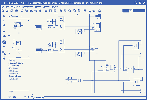
ProfiLab-Expert 4.0
The ProfiLab-Expert software allows you to develop your own digital or analogue measuring technology projects. It doesn't matter if you want to create analogue measurements or digital controls - you can realize it all. And for all this you don't...
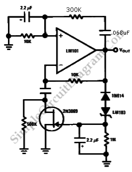
Wien Bridge Sine Wave Oscillator
Achieving the appropriate amplifier loop gain is a significant challenge in generating a low distortion, constant amplitude sine wave. Nevertheless, this issue can be addressed with...
Amplifier loop gain is a critical parameter in the design of audio and signal processing...
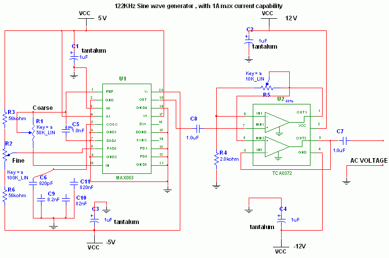
Adjustable High/Low Frequency Sine wave generator
This circuit utilizes the versatile MAX038 function generator. While some advanced features of this integrated circuit (IC) are disabled in this configuration, it is capable of generating sine, triangle, and square waves by adjusting the A0 and A1 pins, as...
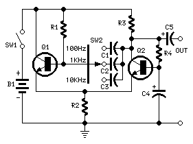
Simple Square wave Generator
This simple circuit generates a good and stable 1V peak-to-peak square wave at 100Hz, 1KHz and 10KHz using a single 1.5V cell as power supply. An useful feature of this circuit is that frequency changes can be obtained by switching...
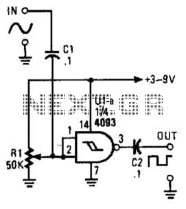
Sine Wave To Square Wave Converter Circuit
This circuit converts a sine wave into a square wave. It consists of a single 2-input NAND Schmitt trigger configured as an inverter, with an adjustable trigger level at its input. As the input voltage exceeds the gate's trigger point,...
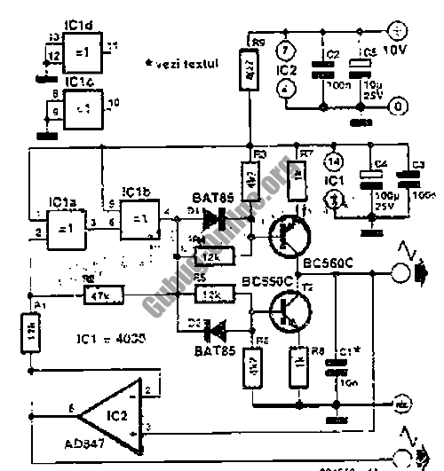
1KHz Square Wave Generator Circuit
This design outlines a simple 1 kHz square wave generator utilizing a few components and the LM3909 integrated circuit, which is beneficial for testing audio equipment. The circuit operates on a single 1.5V battery cell, producing a maximum output signal...
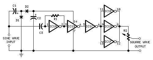
Sine to Square wave Converter
This circuit is intended to provide good square waves converting a sine wave picked up from an existing generator. Its main feature consists in the fact that no power source is needed: thus it can be simply connected between a...
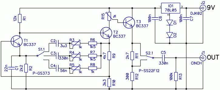
sine wave generator with low distortion
The construction of a low-frequency harmonic signal generator is essential for debugging and measuring audio amplifiers and other circuits.
The low-frequency harmonic signal generator is a critical tool designed to produce stable and precise low-frequency signals, which are crucial for testing...
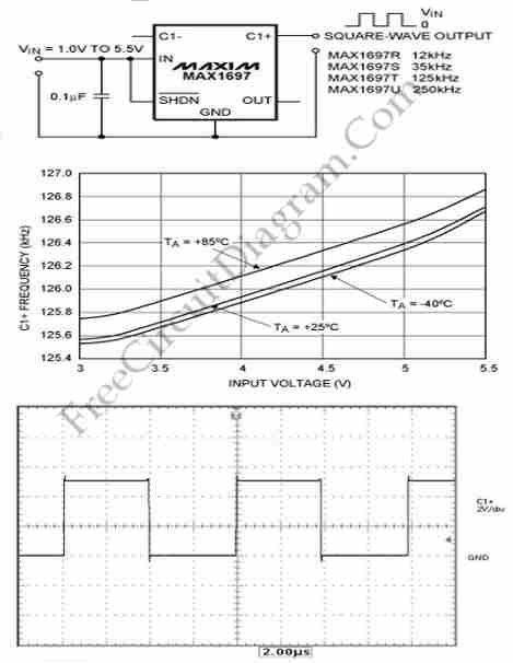
Square Wave Oscillator with Minimum Components Count
This circuit generates a square wave, which is useful as a clock signal or AC drive for the excitation of sensors. This article presents a square wave.
The square wave generator circuit is designed to produce a periodic waveform that alternates...