


5 volt ttl voltage monitor
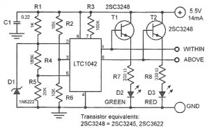
Description: This device is designed to control a supply voltage of +5 V. It provides information signals at TTL levels, accompanied by an LED display that indicates whether the voltage is within the nominal value or deviates from it. The device is housed in a box. The core component of the device is a low-current window comparator IC, the LTC1042 from Linear Technology. The reference voltage is set at 2.5 V ± 0.005 V for the middle window, which is established by zener diode D1 and connected to pin 2 of the comparator. The width of this window is 20% (± 10%) of the reference voltage, which is set using a resistor divider consisting of R4 and R5. The controlled voltage is divided by two resistors, R2 and R6, and fed to pin 3 of the IC. The voltages at terminals 2 and 3 are compared to determine the deviation (10%, output 5). The green LED D2 lights up when the voltage is within the desired range, while the red LED D3 activates when the voltage is out of range.
The described device serves as a voltage monitoring and control system, utilizing a low-current window comparator to ensure that the supply voltage remains stable at +5 V. The LTC1042 comparator is pivotal in this application, as it compares the monitored voltage against a precise reference voltage derived from a zener diode. The choice of a 2.5 V reference allows for a symmetrical window around this value, facilitating effective monitoring of voltage deviations.
The window comparator operates by defining a voltage range that the monitored signal must stay within. The reference voltage is established by the zener diode D1, which provides a stable voltage source. The voltage window is determined by the resistor divider formed by R4 and R5, ensuring that the comparator can detect slight variations in the input voltage. The resistor network formed by R2 and R6 scales the monitored voltage down to a level compatible with the comparator's input range, allowing for accurate comparisons.
The output of the comparator is connected to indicator LEDs. The green LED D2 signifies that the monitored voltage is within the acceptable range, providing a visual confirmation of normal operation. Conversely, the red LED D3 serves as an alert, illuminating when the voltage strays outside the defined limits, thereby enabling immediate corrective actions.
Overall, this voltage monitoring device is essential for applications requiring precise voltage regulation and monitoring, ensuring that the system operates within specified parameters. The use of TTL signal levels for output makes it suitable for integration with digital systems, enhancing its utility in various electronic applications.This is a simple device designed to control supply voltage +5 V Monitor provides information signals TTL level, accompanied by the LED display, indicating that stress or deviated from the nominal value, or vice versa, is in a box . The basis of the device is a low-current window comparator IC LTC1042 company Linear Technology. The reference vol tage is 2. 5 V ± 0. 005 V for the middle window created by zener D1 and fed to pin 2 comparator. The width of this window equal to 20% ( ± 10%) of the reference voltage established at pin 5 chip divider R4, R5. The controlled voltage is divided by two resistors R2 and R6, and fed to pin 3 of the chip. Voltage at the terminals 2 and 3 are compared with the established view of the deviation (10%, output 5).
The green LED D2 is illuminated when the voltage is within the desired range. If the voltage is out of range, red LED D3.
The described device serves as a voltage monitoring and control system, utilizing a low-current window comparator to ensure that the supply voltage remains stable at +5 V. The LTC1042 comparator is pivotal in this application, as it compares the monitored voltage against a precise reference voltage derived from a zener diode. The choice of a 2.5 V reference allows for a symmetrical window around this value, facilitating effective monitoring of voltage deviations.
The window comparator operates by defining a voltage range that the monitored signal must stay within. The reference voltage is established by the zener diode D1, which provides a stable voltage source. The voltage window is determined by the resistor divider formed by R4 and R5, ensuring that the comparator can detect slight variations in the input voltage. The resistor network formed by R2 and R6 scales the monitored voltage down to a level compatible with the comparator's input range, allowing for accurate comparisons.
The output of the comparator is connected to indicator LEDs. The green LED D2 signifies that the monitored voltage is within the acceptable range, providing a visual confirmation of normal operation. Conversely, the red LED D3 serves as an alert, illuminating when the voltage strays outside the defined limits, thereby enabling immediate corrective actions.
Overall, this voltage monitoring device is essential for applications requiring precise voltage regulation and monitoring, ensuring that the system operates within specified parameters. The use of TTL signal levels for output makes it suitable for integration with digital systems, enhancing its utility in various electronic applications.This is a simple device designed to control supply voltage +5 V Monitor provides information signals TTL level, accompanied by the LED display, indicating that stress or deviated from the nominal value, or vice versa, is in a box . The basis of the device is a low-current window comparator IC LTC1042 company Linear Technology. The reference vol tage is 2. 5 V ± 0. 005 V for the middle window created by zener D1 and fed to pin 2 comparator. The width of this window equal to 20% ( ± 10%) of the reference voltage established at pin 5 chip divider R4, R5. The controlled voltage is divided by two resistors R2 and R6, and fed to pin 3 of the chip. Voltage at the terminals 2 and 3 are compared with the established view of the deviation (10%, output 5).
The green LED D2 is illuminated when the voltage is within the desired range. If the voltage is out of range, red LED D3.
5V 0.5A power supply
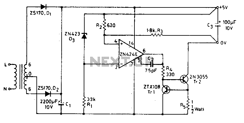
The circuit functions as a constant voltage source, modified by feedback components R2 and R3 to maintain a stable output voltage. The ZN424E output must be at least 2 volts above the negative rail, with the load connected to the...
Four-channel-comparator
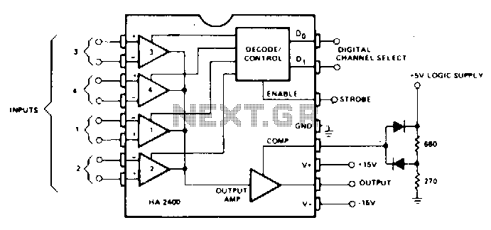
When operated as an open loop without compensation, the HA-2400 functions as a comparator with four selectable input channels. The clamping network at the compensation pin limits the output voltage, enabling DTL or TTL digital circuits to be driven with...
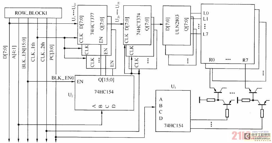
Large-scale LED display system hardware structure and principle
The large-scale LED display system utilizes a line-by-line scanning method and outlines the driving mechanisms to reduce hardware costs. It employs a 1/16 non-interlaced scanning mode, accommodating a total of 16 LED display panels. The schematic diagram of the driver...
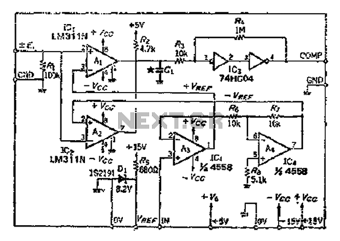
The reference voltage of the symmetrical bipolar comparator
An AI comparator input is connected to a reference resistor (Rl). When the output reaches a specified level, known as VREP (absolute value), the output also stabilizes at this level. The outputs Ai and As are connected to an OR...
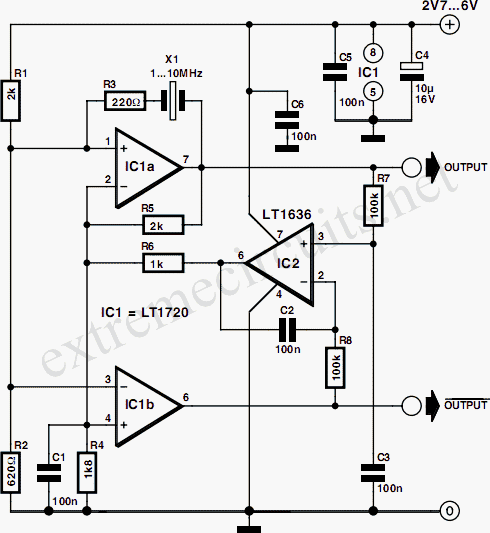
Comparator Based Crystal Oscillator
A simple crystal oscillator can be constructed using a comparator from the LT1720/LT1721 series; however, this design may encounter several inherent limitations and issues. While the LT1720/LT1721 provides the correct logic output when one input falls outside the common mode...
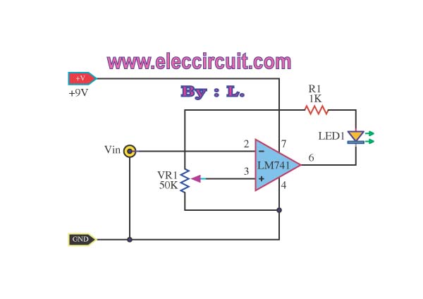
Battery voltage monitor circuit by LM339
This simple low voltage tester circuit can be used to monitor batteries and other voltage sources for issues, utilizing an LED display and alarm sound.
The low voltage tester circuit is designed to provide a reliable method for monitoring the voltage...
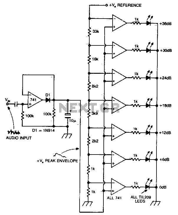
LED bar peak program meter display for audio
A vertical column of LEDs is configured so that as the audio signal level rises, an increasing number of LEDs illuminate. The LEDs are arranged in increments of 6 dB. The circuit features a fast response time and a one-second...
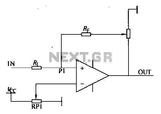
Loop comparator circuit
Environmental interference can affect the transfer switching, leading to the production of burrs in confidence disgrace. The switch position signal will control the computer system with the reliability of lanthanum burrs. The work has some impact. Glitches are typically addressed...
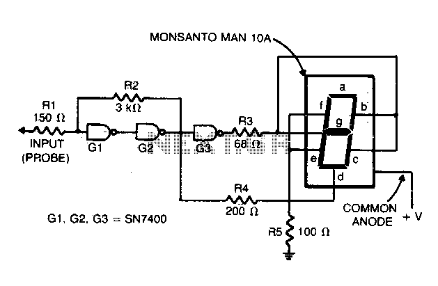
Ttl logic tester
Gates G1 and G2, along with resistors R1 and R2, create a straightforward voltage monitor with a trip point set at 1 volt. Gate G3 functions as an inverter. The display section of the tester features a common anode alphanumeric...