


555 Pocket digital frequency meter schematic
#555 timer
#frequency meter
#quartz crystal
#digital measurement
#test circuit
#electronic watch
#signal measurement
#DIY instrument
#precision measurement
#counter circuit
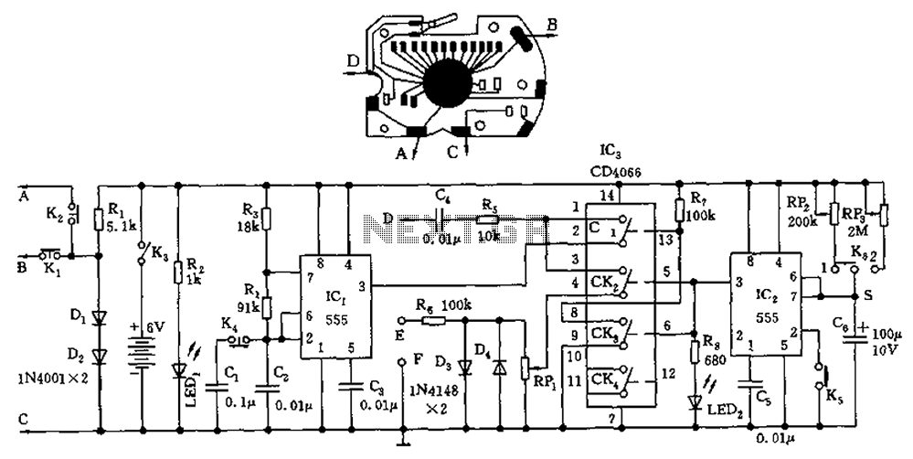
Description: A circuit utilizing a standard digital quartz electronic watch, with its crystal soldered, forms a digital frequency meter as illustrated by the connected circuit. The test signal is applied to the E and F sides via components such as R6, D3, and D4, which act as limiters, while RP1 is used to control the input signal's intensity. During measurement, pressing K5 activates the IC2 monostable delay circuit, with four analog switches (CD4066) operating in a specific configuration: CK2 and CK3 are closed, CK1 is open, thus isolating the core of the memory circuit. The measured signal is routed through CK2, R5, and C4 to establish the core of the D point, initiating the core division and starting the counting circuit. After a preset duration, pin 3 of IC2 goes low, turning off CK2 and CK3, while closing CK1, which stores the measured signal in memory. To read the frequency, pressing K4 displays the measured signal frequency on the liquid crystal display (LCD). The timing switch K6 is divided into two intervals: 33 seconds and 328 seconds. During calibration, RP3 is adjusted for the 328-second timing, and RP2 is adjusted for the 33-second timing. The positive terminal connects to the electronic watch, the B point connects to the upper function key core, the C point connects to the negative reed core, and the D point connects to any of the quartz crystal pads. The LCD reading indicates that for one file, the value is multiplied by 1000 Hz, and for two files, it is multiplied by 100 Hz.
The described circuit operates as a digital frequency meter by leveraging the components of a standard digital quartz watch. The initial configuration involves soldering the quartz crystal, which is essential for the oscillator's function. The test signal is applied to designated points (E and F) through resistors and diodes that limit the signal strength, ensuring accurate measurements without overloading the circuit. The variable resistor RP1 allows for fine-tuning of the input signal, which is crucial for obtaining reliable frequency readings.
Upon activating the measurement process by pressing switch K5, the monostable delay circuit (IC2) is triggered, which sets the timing for the measurement. The analog switches (CK1, CK2, CK3) play a vital role in controlling the flow of the signal through the circuit, with CK2 and CK3 allowing the signal to pass while isolating the core memory circuit. This configuration ensures that the signal is processed correctly for frequency counting.
The integration of R5 and C4 serves to shape the signal for the counting circuit, establishing the necessary conditions for accurate frequency measurement. The counting circuit operates based on the input signal until the preset time elapses, at which point the state of the circuit changes to store the measured frequency in memory. This is indicated by the low signal from pin 3 of IC2, which disables the counting function and enables the storage of the frequency data.
To retrieve and display the measured frequency, the user presses K4, which activates the LCD to show the results. The circuit is designed to provide readings at two different scales: one file corresponds to a frequency multiplied by 1000 Hz, while two files correspond to a frequency of 100 Hz, allowing for versatile applications.
The timing switch K6 facilitates two distinct measurement periods, enhancing the circuit's functionality for various testing scenarios. The adjustments made via RP2 and RP3 during calibration ensure the accuracy of the timing intervals, which are critical for precise frequency measurement.
Overall, this circuit exemplifies an innovative use of digital watch components to create a practical and efficient frequency meter, showcasing the versatility and adaptability of electronic components in measurement applications. Circuit using an ordinary digital quartz electronic watch, the lower its crystal welding, as shown by the connected circuit constitutes a digital frequency meter. The test sign al is applied to E, F side by R6, D3, D4, etc. limiter, and adjust RP1, control the intensity of the input signal. When measuring, click K5, the IC2 monostable delay circuit is set, four analog switch IC3 (CD4066) of CK2, CK3 closed, CK1 off, form the core of memory circuit is cut off, the signal being measured by CK2, R5, C4 is added to form the core of the D point, form the core division, counting circuit starts operating. To be a preset time, IC2 of 3 feet referred to the low level, CK2, CK3 off, CK1 is closed, the signal to be measured into the memory state.
When reading, just click K4, the liquid crystal display panel will show the frequency of the signal to be measured. The timing switch K6 is divided into two tranches of 33 seconds and 328 seconds. When debugging, adjust RP3 at the second speed, timing of 328 seconds; adjust RP2 at the first speed for 33 seconds.
A positive figure point of access electronic watch, B point of access form the core of the upper end of the function keys, C point of access form the core negative reed, D point of access to any foot pads quartz crystal. The reading on the LCD screen when a file, the value is multiplied by the frequency 1000Hz, the value is multiplied by 2 files 100Hz.
The described circuit operates as a digital frequency meter by leveraging the components of a standard digital quartz watch. The initial configuration involves soldering the quartz crystal, which is essential for the oscillator's function. The test signal is applied to designated points (E and F) through resistors and diodes that limit the signal strength, ensuring accurate measurements without overloading the circuit. The variable resistor RP1 allows for fine-tuning of the input signal, which is crucial for obtaining reliable frequency readings.
Upon activating the measurement process by pressing switch K5, the monostable delay circuit (IC2) is triggered, which sets the timing for the measurement. The analog switches (CK1, CK2, CK3) play a vital role in controlling the flow of the signal through the circuit, with CK2 and CK3 allowing the signal to pass while isolating the core memory circuit. This configuration ensures that the signal is processed correctly for frequency counting.
The integration of R5 and C4 serves to shape the signal for the counting circuit, establishing the necessary conditions for accurate frequency measurement. The counting circuit operates based on the input signal until the preset time elapses, at which point the state of the circuit changes to store the measured frequency in memory. This is indicated by the low signal from pin 3 of IC2, which disables the counting function and enables the storage of the frequency data.
To retrieve and display the measured frequency, the user presses K4, which activates the LCD to show the results. The circuit is designed to provide readings at two different scales: one file corresponds to a frequency multiplied by 1000 Hz, while two files correspond to a frequency of 100 Hz, allowing for versatile applications.
The timing switch K6 facilitates two distinct measurement periods, enhancing the circuit's functionality for various testing scenarios. The adjustments made via RP2 and RP3 during calibration ensure the accuracy of the timing intervals, which are critical for precise frequency measurement.
Overall, this circuit exemplifies an innovative use of digital watch components to create a practical and efficient frequency meter, showcasing the versatility and adaptability of electronic components in measurement applications. Circuit using an ordinary digital quartz electronic watch, the lower its crystal welding, as shown by the connected circuit constitutes a digital frequency meter. The test sign al is applied to E, F side by R6, D3, D4, etc. limiter, and adjust RP1, control the intensity of the input signal. When measuring, click K5, the IC2 monostable delay circuit is set, four analog switch IC3 (CD4066) of CK2, CK3 closed, CK1 off, form the core of memory circuit is cut off, the signal being measured by CK2, R5, C4 is added to form the core of the D point, form the core division, counting circuit starts operating. To be a preset time, IC2 of 3 feet referred to the low level, CK2, CK3 off, CK1 is closed, the signal to be measured into the memory state.
When reading, just click K4, the liquid crystal display panel will show the frequency of the signal to be measured. The timing switch K6 is divided into two tranches of 33 seconds and 328 seconds. When debugging, adjust RP3 at the second speed, timing of 328 seconds; adjust RP2 at the first speed for 33 seconds.
A positive figure point of access electronic watch, B point of access form the core of the upper end of the function keys, C point of access form the core negative reed, D point of access to any foot pads quartz crystal. The reading on the LCD screen when a file, the value is multiplied by the frequency 1000Hz, the value is multiplied by 2 files 100Hz.
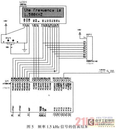
Design on the basis of the mechanically controlled digital frequency meter of one piece
The primary function of the frequency counter is to measure the frequency and cycle of a signal. Its applications span a wide range, extending beyond simple instrument measurements to areas such as education, scientific research, high-precision instrument measurement, and industrial...
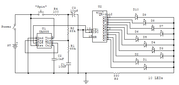
555 timer Electronic roulette wheel circuit and explanation
This electronic circuit is a simplified version of an electronic roulette game, utilizing the 4017 integrated circuit (IC), which functions as a 10-stage decade counter/divider. It is driven by a versatile 555 IC configured as a voltage-controlled oscillator (VCO). The...
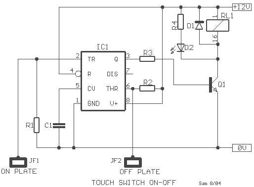
Touch Switch with 555
The modern mechanic switches are improved concerning old technology. We need, however, many times to replace some old switch or to check currents bigger than the durability of certain switches or simply we need something with a modern appearance. For...
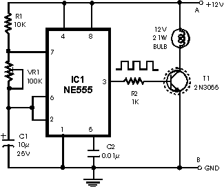
Brakelight Stop flasher
This is basically a flasher circuit modified to turn on and off a bulb instead of a LED. It uses a 555 timer IC working as an astable multivibrator. The flashing rate can be varied from very fast to a...
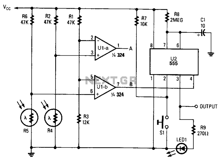
Monostable circuit diagram of a light control
A combined monostable multivibrator using the 555 timer integrated circuit, along with a pair of light control comparators. This circuit can be utilized to control a load based on the timing parameters set within the circuit.
The circuit comprises a 555...
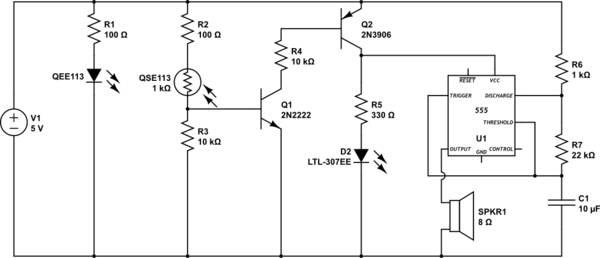
transistors IR Emitter/Detector with 555 timer alarm
This circuit detects when a tube is empty and pulses a piezo buzzer at 5-second intervals. It is currently operational with a 5V supply on a breadboard but needs to be adapted for a 12V supply from a wall wart....
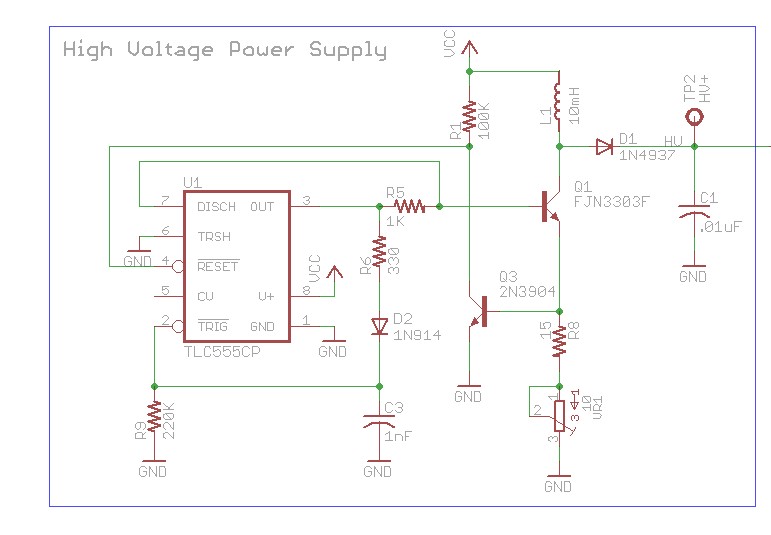
Using microcontroller as oscillator for high voltage power suppy
The design involves using a 555 timer as an oscillator in the high voltage power supply section. There is a query regarding the possibility of altering the design to utilize an output from a microcontroller to generate an oscillating signal...
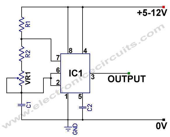
555 Variable Frequency Square Wave Generator
555 Variable Frequency Square Wave Generator. This simple 555 Variable Frequency Square Wave Generator produces a variable frequency output.
The 555 Variable Frequency Square Wave Generator is a versatile circuit that utilizes the 555 timer IC to generate square wave signals...
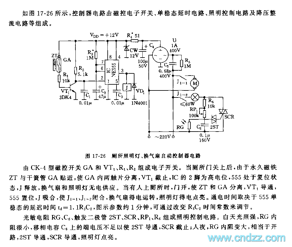
555 toilet floodlight and ventilator automatic control circuit
The electronic switch consists of the CK-4 type magnetic control switch and the components VT1, R1, and R2. When the bathroom door is closed, the permanent magnet ZT and the reed switch GA come into proximity, which separates the two...