


60MHz Frequency Meter / Counter 10Hz to 60MHz
#frequency meter
#counter
#microcontroller
#LCD display
#auto-ranging
#frequency measurement
#input protection
#precision measurement
#electronics testing
#signal analysis
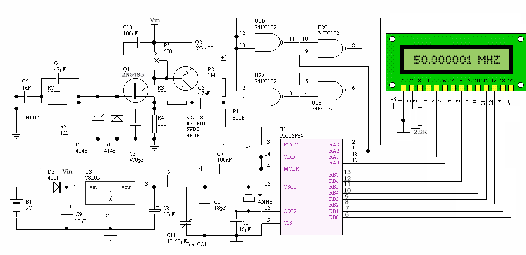
Description: This project is a compact frequency counter capable of measuring frequencies from 1 Hz to 50 MHz, modified from the original design by Weeder Technologies. A new PCB has been designed to accommodate a 16x1 LCD, and the source code has been altered for compatibility with the new compact PCB specifications. Features include auto-ranging with a floating decimal point, the ability to display up to 7 digits on a 1x16 LCD, and auto-adjusting gate speed ranging from 0.1 seconds to 1 second. The microcontroller-based circuitry ensures simplicity, ease of assembly, and highly stable readouts. The device has a sensitivity of approximately 100 mV RMS for frequencies between 100 Hz and 2 MHz, and 800 mV RMS at 50 MHz. Input overload protection is also included. The LCD display connects to the PCB via a 16-pin male and female header, making it easily detachable from the main board. The 16-pin male header must be soldered to the LCD display, while the 16-pin female header must be soldered to the PCB.
The frequency counter circuit is designed around a microcontroller that processes the incoming frequency signals and displays the results on a 16x1 LCD. The microcontroller is programmed to handle the auto-ranging feature, which allows the device to automatically adjust its measurement range based on the frequency detected. This is particularly useful for users who require precision across a broad spectrum of frequencies.
The PCB layout has been optimized for compactness, ensuring that the components are arranged efficiently to minimize signal interference and improve performance. The microcontroller interfaces with the LCD through a dedicated data bus, which transmits the frequency readings. The use of a floating decimal point in the display enhances readability, allowing users to quickly interpret the frequency measurements.
The input stage of the frequency counter includes a sensitivity circuit that can detect low-level signals, with an RMS sensitivity of 100 mV for frequencies up to 2 MHz. This sensitivity increases to 800 mV at the maximum frequency of 50 MHz, ensuring accurate readings across the entire operational range. Additionally, the input overload protection circuit safeguards the device against excessive input signals, preventing damage to the microcontroller and other sensitive components.
The detachable LCD feature, facilitated by the 16-pin headers, allows for easy assembly and maintenance. The male header is soldered to the LCD, while the female header is soldered to the PCB, providing a secure yet removable connection. This design choice not only simplifies repairs but also allows users to replace the LCD if necessary without extensive modifications to the circuit.
Overall, this frequency counter project combines advanced features with user-friendly design, making it an effective tool for a variety of applications in electronics testing and measurement.This project is nice and small frequency counter that reads frequency from 1 Hz to 50 MHz that I have modified from original designed by Weeder Technologies . I have designed new PCB to fit with 16X1 LCD and change source code for compatible with new small PCB Specifications - Auto-ranging with floating decimal point.
- Up to 7 digits displayed on 1X16 LCD. - Auto-adjusting gate speed (0.1 sec to 1 sec). - Microcontroller-based circuitry provides for simplicity, ease of assembly, and highly stable readout. - Sensitivity approximately 100 mV RMS (100 Hz to 2 MHz), 800 mV RMS @ 50 MHz. - Input overload protected. LCD display is connected to PCB by 16-PIN male & female header and is easily detachable from the main board. 16-PIN Male Header must be soldered to LCD display. 16-PIN Female Header must be soldered to PCB.
The frequency counter circuit is designed around a microcontroller that processes the incoming frequency signals and displays the results on a 16x1 LCD. The microcontroller is programmed to handle the auto-ranging feature, which allows the device to automatically adjust its measurement range based on the frequency detected. This is particularly useful for users who require precision across a broad spectrum of frequencies.
The PCB layout has been optimized for compactness, ensuring that the components are arranged efficiently to minimize signal interference and improve performance. The microcontroller interfaces with the LCD through a dedicated data bus, which transmits the frequency readings. The use of a floating decimal point in the display enhances readability, allowing users to quickly interpret the frequency measurements.
The input stage of the frequency counter includes a sensitivity circuit that can detect low-level signals, with an RMS sensitivity of 100 mV for frequencies up to 2 MHz. This sensitivity increases to 800 mV at the maximum frequency of 50 MHz, ensuring accurate readings across the entire operational range. Additionally, the input overload protection circuit safeguards the device against excessive input signals, preventing damage to the microcontroller and other sensitive components.
The detachable LCD feature, facilitated by the 16-pin headers, allows for easy assembly and maintenance. The male header is soldered to the LCD, while the female header is soldered to the PCB, providing a secure yet removable connection. This design choice not only simplifies repairs but also allows users to replace the LCD if necessary without extensive modifications to the circuit.
Overall, this frequency counter project combines advanced features with user-friendly design, making it an effective tool for a variety of applications in electronics testing and measurement.This project is nice and small frequency counter that reads frequency from 1 Hz to 50 MHz that I have modified from original designed by Weeder Technologies . I have designed new PCB to fit with 16X1 LCD and change source code for compatible with new small PCB Specifications - Auto-ranging with floating decimal point.
- Up to 7 digits displayed on 1X16 LCD. - Auto-adjusting gate speed (0.1 sec to 1 sec). - Microcontroller-based circuitry provides for simplicity, ease of assembly, and highly stable readout. - Sensitivity approximately 100 mV RMS (100 Hz to 2 MHz), 800 mV RMS @ 50 MHz. - Input overload protected. LCD display is connected to PCB by 16-PIN male & female header and is easily detachable from the main board. 16-PIN Male Header must be soldered to LCD display. 16-PIN Female Header must be soldered to PCB.
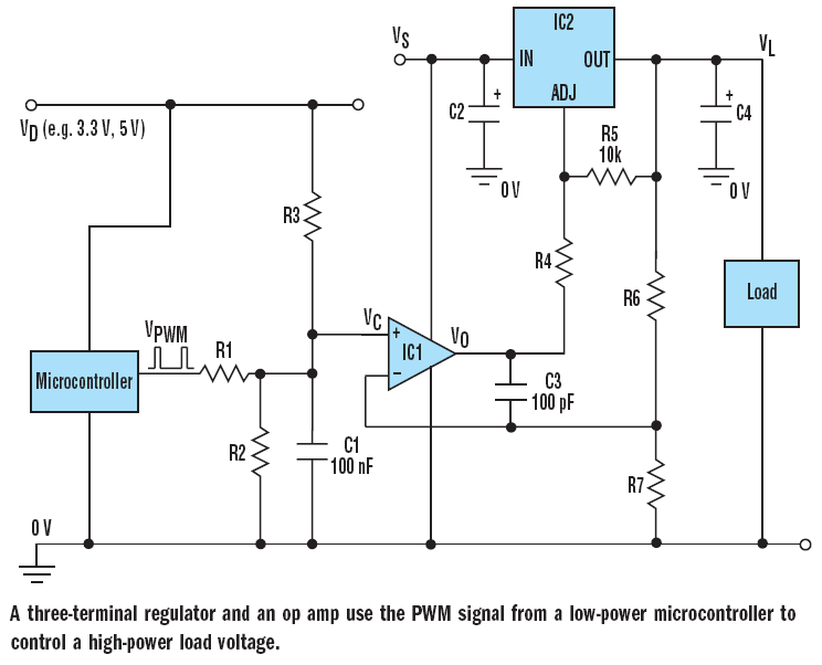
microcontroller How does this power supply circuit work? (MCU + LM317)
The filter consisting of resistors R1, R2, and capacitor C1 integrates the PWM waveform. The purpose of the operational amplifier appears to be that of a non-inverting amplifier, with the gain determined by resistors R6 and R7. However, the need...
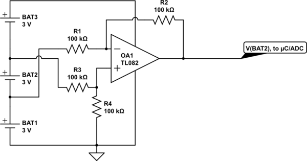
integrated circuit Improving absolute precision of ADC to balance battery voltage
Utilize a high-performance microcontroller (Piccolo TMS320F28035, 12-bit resolution, +/- 4 LSB offset, +/- 60 LSB gain) to measure the voltage across stacked battery cells and control related analog electronics for charge equalization. The microcontroller will also save data in EEPROM...
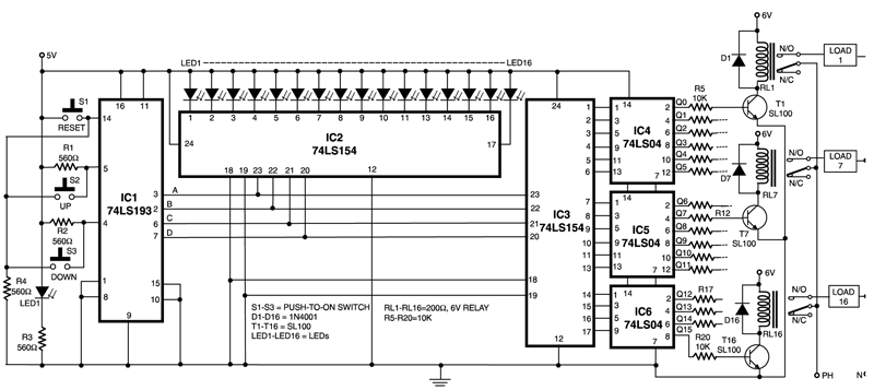
digital switching system
This circuit is capable of controlling one out of 16 devices using two push-to-on switches. An up/down counter functions as the master controller for the system, and visual feedback is provided through LEDs. The circuit employs IC1 (74LS193), which is...
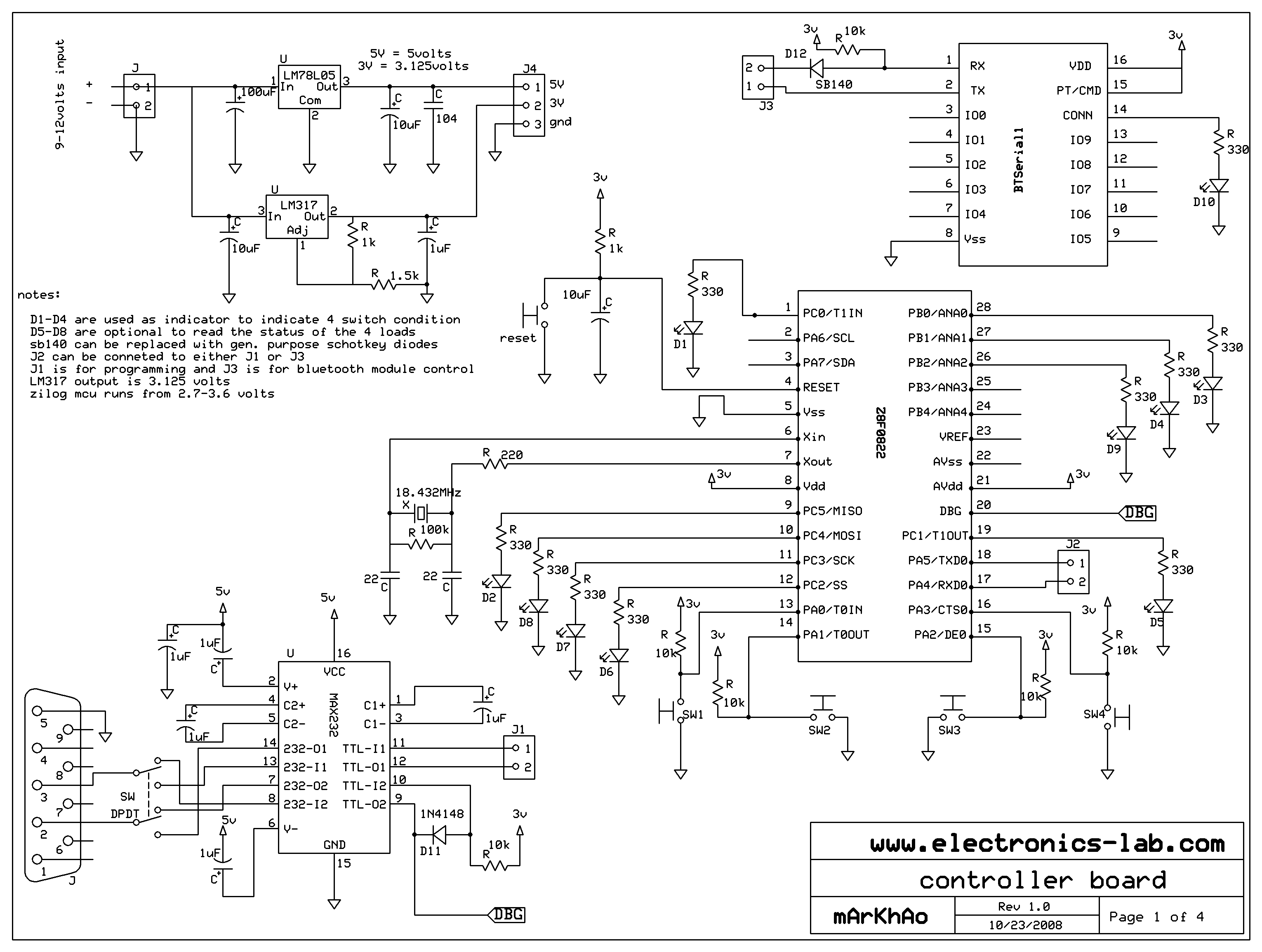
MCU controlled Bluetooth automation
The microcontroller used is 0822 zilog encore! 8k series (soic,28pin) as shown on the figure. Is a programmable microcontroller, the functions used are the GPIO and the UART of the chip. GPIO is used on led indicators, and the UART...
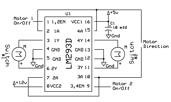
Automatic Switch Project
Model railroad turnouts, often referred to as switches, can be controlled in various ways. The simplest method is manual control, operated by hand. Remote activation is typically achieved through pneumatic (air) or electrical means. The project discussed in these articles...
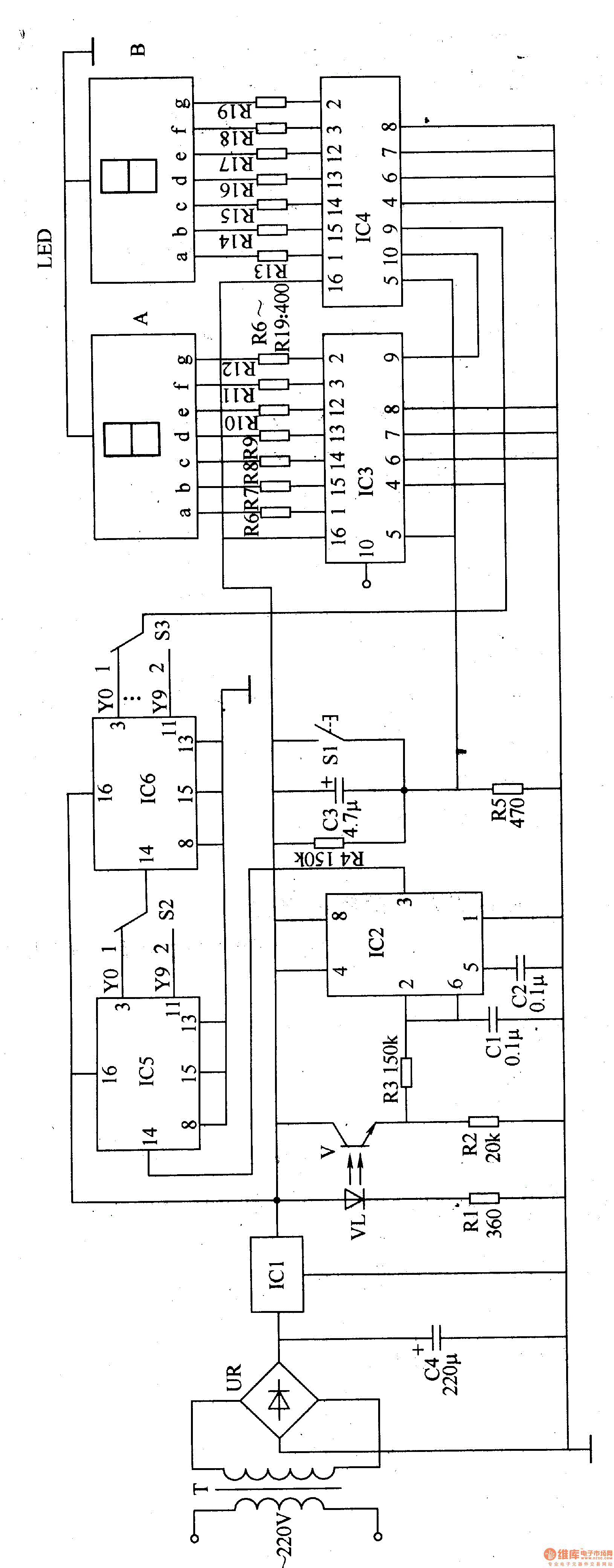
Winding electronic counter 2
The electronic counter of the winding machine utilizes an LED digital display to indicate the number of turns of the wound coil, with a maximum counting capacity of 9900 turns. The operational principle of the winding machine circuit consists of...
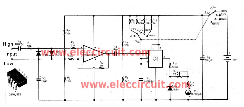
Cheap frequency meter by CA3130
This inexpensive frequency meter circuit is suitable for general use in small laboratories. It is cost-effective, easy to construct, and sufficiently reliable for most electronics enthusiasts. The frequency can be directly read from the meter, with a measurement range from...
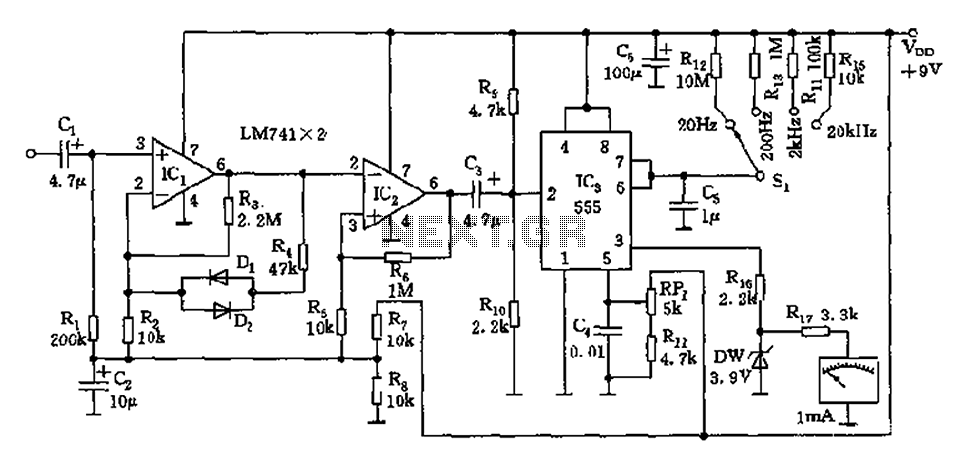
555 direct reading frequency meter schematic
The circuit is a direct-reading frequency meter that utilizes an amplifier and a one-shot trigger circuit, along with table-top components. It is capable of directly detecting a 1mA signal at the read head, with a maximum signal frequency of up...
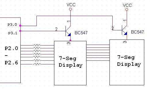
Interfacing seven segment to microcontroller
The Tutorial shows how to interface 7-segment display to a microcontroller. Also explains how do display more than one 7-segment on same data lines using scanning method. 7 Seg displays are are basically 7 LED's. It will be much easier...