


AD2S80A typical connection circuit
#AD2S80A
#resolver
#12bit
#peripheral connectivity
#device parameters
#sensor interface
#signal processing
#circuit design
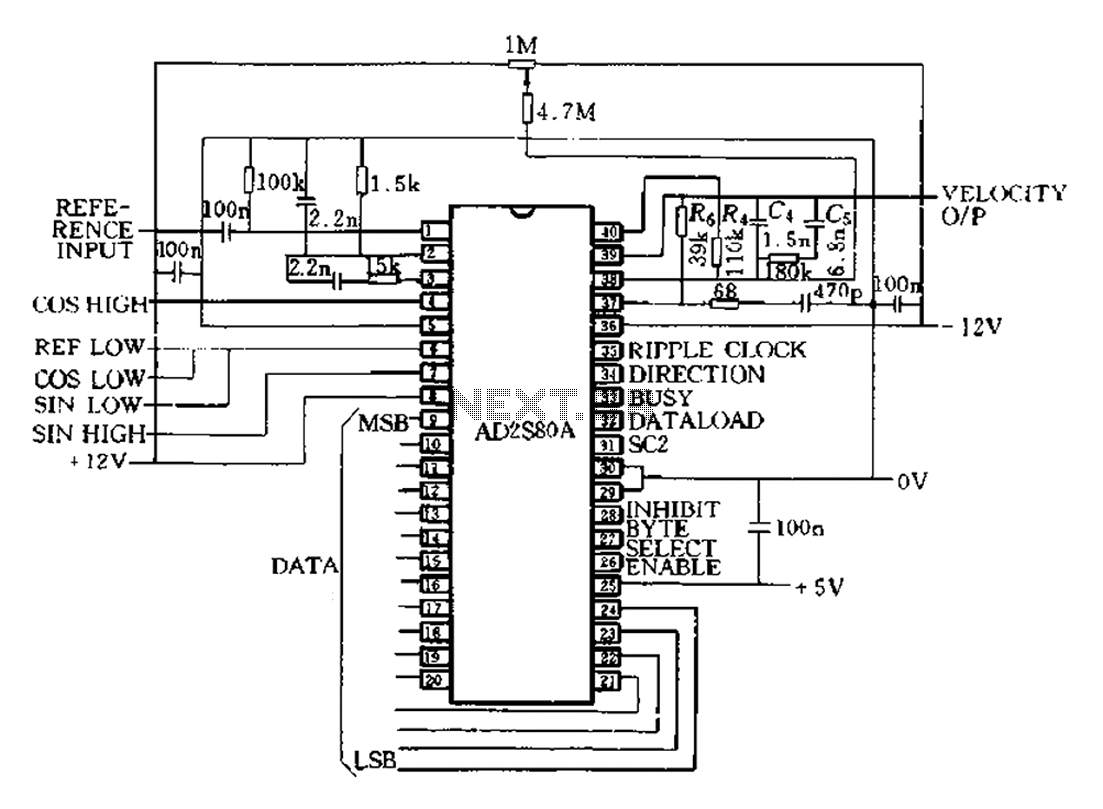
Description: The AD2S80A represents a typical application circuit, detailing specific peripheral connectivity and device parameters. It is configured for a 12-bit resolution (SCl-0, Sc2 1) to select a reference frequency of 5 kHz. The bandwidth is 520 Hz, with a maximum tracking speed of 260 R/s. The tracking type servo loop RDC is characterized as static and uniform, ensuring that position and velocity measurements do not introduce errors. However, during acceleration, positional errors may occur, which are influenced by the converter's acceleration factor, KA.
The AD2S80A is a high-performance resolver-to-digital converter (RDC) designed for precise angular position measurement in various applications, including robotics and industrial automation. The device operates with a 12-bit resolution, allowing for fine granularity in position tracking. The reference frequency of 5 kHz is optimal for many dynamic applications, providing a good balance between responsiveness and signal integrity.
The specified bandwidth of 520 Hz indicates the frequency range over which the RDC can accurately track changes in position. This is crucial in high-speed applications where rapid changes in position must be monitored without lag. The maximum tracking speed of 260 R/s ensures that the system can handle fast movements, making it suitable for applications that require quick adjustments and high precision.
The static and uniform operation of the RDC ensures that under stable conditions, the system can maintain accurate readings without introducing errors. This characteristic is essential for applications where consistent performance is critical. However, it is important to note that during acceleration, additional positional errors can arise. These errors can be quantified through the converter's acceleration factor, KA, which relates the rate of change in position to the resulting angle error. Understanding this relationship is vital for engineers when designing systems that require high precision in dynamic conditions.
Incorporating the AD2S80A into a system involves careful consideration of the peripheral connectivity, ensuring that the device interfaces correctly with other components such as microcontrollers or digital signal processors. Proper implementation of the device parameters is essential for achieving optimal performance and minimizing errors in position tracking, particularly in applications that involve rapid acceleration or deceleration.AD2S80A represents a typical application circuit, give a specific peripheral connectivity and device parameters. As illustrated, it is provided 12bit (SCl-0, Sc2 1), to select the reference frequency 5kHz. Bandwidth is 520Hz, maximum tracking speed 260R/s. As described above, since the tracking type servo loop RDC is l, static and uniform work, the position and velocity without introducing errors. But when accelerating position will produce additional errors. This additional angle error is determined by the converter acceleration factor KA.
The AD2S80A is a high-performance resolver-to-digital converter (RDC) designed for precise angular position measurement in various applications, including robotics and industrial automation. The device operates with a 12-bit resolution, allowing for fine granularity in position tracking. The reference frequency of 5 kHz is optimal for many dynamic applications, providing a good balance between responsiveness and signal integrity.
The specified bandwidth of 520 Hz indicates the frequency range over which the RDC can accurately track changes in position. This is crucial in high-speed applications where rapid changes in position must be monitored without lag. The maximum tracking speed of 260 R/s ensures that the system can handle fast movements, making it suitable for applications that require quick adjustments and high precision.
The static and uniform operation of the RDC ensures that under stable conditions, the system can maintain accurate readings without introducing errors. This characteristic is essential for applications where consistent performance is critical. However, it is important to note that during acceleration, additional positional errors can arise. These errors can be quantified through the converter's acceleration factor, KA, which relates the rate of change in position to the resulting angle error. Understanding this relationship is vital for engineers when designing systems that require high precision in dynamic conditions.
Incorporating the AD2S80A into a system involves careful consideration of the peripheral connectivity, ensuring that the device interfaces correctly with other components such as microcontrollers or digital signal processors. Proper implementation of the device parameters is essential for achieving optimal performance and minimizing errors in position tracking, particularly in applications that involve rapid acceleration or deceleration.AD2S80A represents a typical application circuit, give a specific peripheral connectivity and device parameters. As illustrated, it is provided 12bit (SCl-0, Sc2 1), to select the reference frequency 5kHz. Bandwidth is 520Hz, maximum tracking speed 260R/s. As described above, since the tracking type servo loop RDC is l, static and uniform work, the position and velocity without introducing errors. But when accelerating position will produce additional errors. This additional angle error is determined by the converter acceleration factor KA.
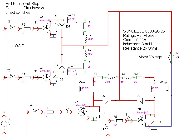
case stepper
Beige Bag Software has been offering affordable and innovative circuit design tools since 1990. B2 Spice provides schematics as well as analog, digital, and mixed-mode electronic circuit simulation. It integrates with EAGLE and CADSTAR PCB software.
B2 Spice is a powerful...
Electronic Projects
This program includes circuit design CAD, simulation, and auto-routing PC layout. PSPICE is also utilized at Unisys, which offers more capabilities but costs six times as much and requires annual renewal. With these requirements and others in mind, a variation...
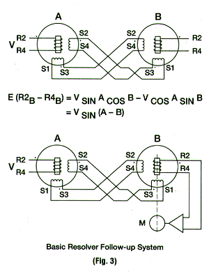
Resolver Application Data
Application notes on resolvers as devices for velocity and position encoding, including potentiometers, incremental encoders, absolute encoders, resolvers, and inductosyns.
Resolvers are electromechanical devices that convert angular position or velocity into an electrical signal. They are commonly used in applications requiring...
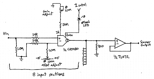
Interpolating Scanner Circuit
This design is for an interpolating scanner, a circuit featuring multiple signal inputs, a control voltage input, and a signal output. The output selectively transitions between inputs, smoothly fading from one to the next as the control voltage increases. A...