


Cable Tester Circuit
#cable tester
#op-amp
#window comparator
#LED indicators
#short-circuit detection
#open-circuit detection
#conductors
#testing
#diagnostics
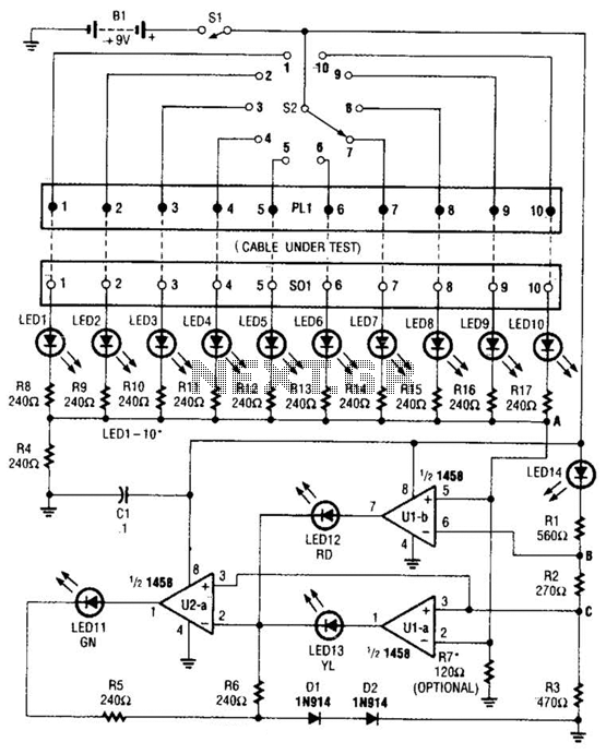
Description: The cable tester utilizes two operational amplifiers (op-amps) configured as window comparators to detect short or open circuit conditions. A third op-amp comparator is employed to indicate a properly functioning circuit, meaning it is neither open nor shorted. Colored light-emitting diodes (LEDs) are used to represent the status of individual conductors within the cable being tested: a red LED indicates a short between conductors, a yellow LED signifies an open conductor, and a green LED shows that the conductor is functioning correctly. Additionally, a bar-graph display with individual LEDs is implemented to indicate which specific conductor in the cable is currently being tested.
The cable tester circuit is designed for efficient and reliable testing of cable integrity. The two op-amps configured as window comparators are set up to monitor the voltage levels across the cable conductors. When a short circuit occurs, the voltage level drops below a predefined threshold, triggering the red LED to illuminate, signaling the presence of a fault. Conversely, if an open circuit is detected, the voltage remains above the threshold, and the yellow LED is activated to indicate an open conductor.
The third op-amp comparator plays a crucial role in verifying the integrity of the circuit. It ensures that when all conductors are intact, the green LED lights up, providing a clear visual indication that the cable is functioning as intended.
The inclusion of a bar-graph display enhances the usability of the tester by allowing for real-time monitoring of each conductor's status. Each LED in the bar-graph corresponds to a specific conductor, illuminating sequentially as the tester cycles through the conductors. This feature not only facilitates quick identification of faults but also provides a comprehensive overview of the cable's condition.
Overall, the design of this cable tester emphasizes clarity and functionality, utilizing simple yet effective components to deliver accurate testing results. The use of color-coded LEDs and a bar-graph display ensures that users can easily interpret the status of the cable under test, making it an invaluable tool for technicians and engineers in the field of electronics. At the heart of the cable tester are two op amps, which are used as a window- comparator to indicate a short- or open-circuit condition. A third op-amp comparator is used to indicate a good circuit (i.e., neither open nor shorted). Colored LEDs are used to show the condition of individual conductors within the cable under test; a red one to indicate a short between conductors, a yellow one to identify an open conductor, and a green one to signify that the conductor is okay.
Individual LEDs of a bar-graph display are used to show which conductor in the cable is being tested.
The cable tester circuit is designed for efficient and reliable testing of cable integrity. The two op-amps configured as window comparators are set up to monitor the voltage levels across the cable conductors. When a short circuit occurs, the voltage level drops below a predefined threshold, triggering the red LED to illuminate, signaling the presence of a fault. Conversely, if an open circuit is detected, the voltage remains above the threshold, and the yellow LED is activated to indicate an open conductor.
The third op-amp comparator plays a crucial role in verifying the integrity of the circuit. It ensures that when all conductors are intact, the green LED lights up, providing a clear visual indication that the cable is functioning as intended.
The inclusion of a bar-graph display enhances the usability of the tester by allowing for real-time monitoring of each conductor's status. Each LED in the bar-graph corresponds to a specific conductor, illuminating sequentially as the tester cycles through the conductors. This feature not only facilitates quick identification of faults but also provides a comprehensive overview of the cable's condition.
Overall, the design of this cable tester emphasizes clarity and functionality, utilizing simple yet effective components to deliver accurate testing results. The use of color-coded LEDs and a bar-graph display ensures that users can easily interpret the status of the cable under test, making it an invaluable tool for technicians and engineers in the field of electronics. At the heart of the cable tester are two op amps, which are used as a window- comparator to indicate a short- or open-circuit condition. A third op-amp comparator is used to indicate a good circuit (i.e., neither open nor shorted). Colored LEDs are used to show the condition of individual conductors within the cable under test; a red one to indicate a short between conductors, a yellow one to identify an open conductor, and a green one to signify that the conductor is okay.
Individual LEDs of a bar-graph display are used to show which conductor in the cable is being tested.
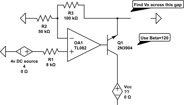
op amp Find Vo in an op-amp transistor circuit
The voltage measured at 12V after the emitter is perplexing, especially when the output from the op-amp is +15V, suggesting a 3V drop across the transistor. This raises questions about the expected gain of 2, which would imply an output...
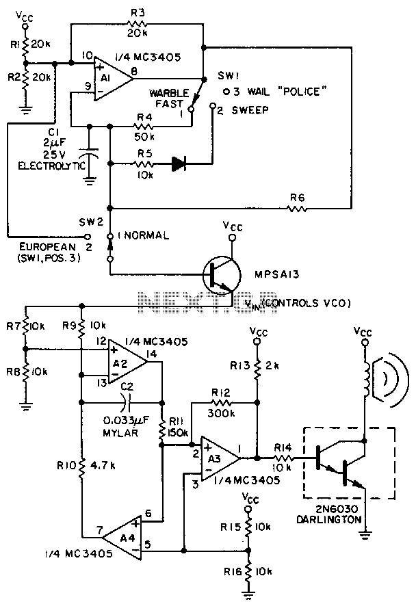
Linear-ic-siren
A low-frequency op-amp oscillator and a voltage-controlled oscillator (VCO), both configured using a single MC3405 dual op-amp and dual comparator, are the primary components in a siren circuit capable of producing various warbles and wails, or functioning as an audio...

All-analog automatic night light circuit
Approximately ten days ago, an all-linear automatic night light circuit was installed to control the lights in the living room. The circuit comprises three operational amplifiers (op-amps): two configured as voltage followers and one as a comparator. As depicted in...

Guitar Control
The IC1A operational amplifier is configured as an inverting amplifier, with its gain determined by a three-way switch that connects different resistor values in parallel to R4. Following this input stage is an active three-band tone control circuit, designed to...
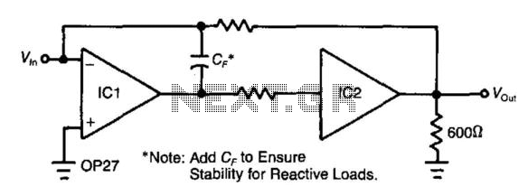
Precision-Increasing Buffer
Adding a unity-gain buffer to an analog circuit can enhance its precision. For instance, the operational amplifier IC1 has a maximum offset voltage drift of 1.8 µV/°C and can drive a 600-ohm load. Under these conditions, IC1 would dissipate 94...
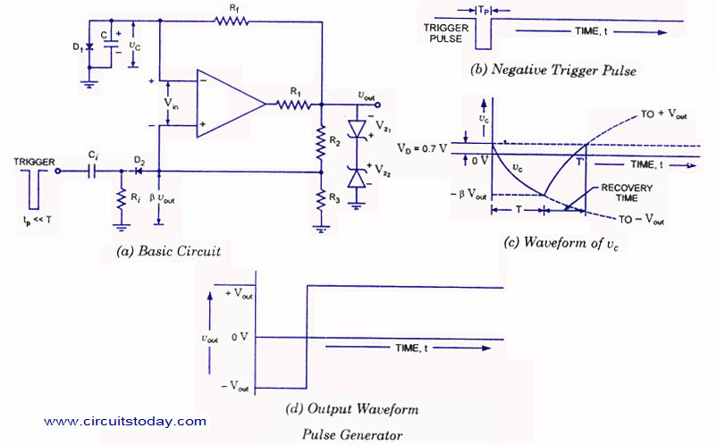
Pulse Generator using Op-Amp
A monostable multivibrator (MMV) features one stable state and one quasi-stable state. The circuit remains in its stable state until an external triggering pulse prompts a transition to the quasi-stable state. After a designated time period T, the circuit returns...

3 Band Graphic Equalizer
This simple equalizer circuit utilizes a single operational amplifier (op-amp) to provide three distinct frequency ranges: low frequency, mid frequency, and high frequency. With the specified component values, the circuit is capable of delivering an approximate gain of +/-20dB at...
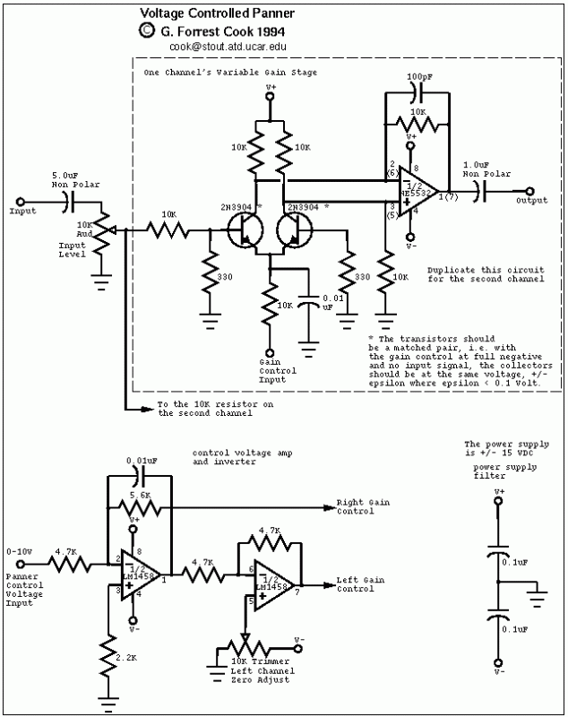
Voltage Controlled Panner
The control voltage is fed into the first half of a 1458 op-amp, this stage inverts the signal and sets the offset and gain for the right channel gain control circuit. This signal is then fed into the second half...
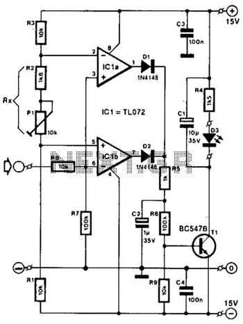
Overload Indicator Circuit
Two operational amplifiers are utilized as comparators to signal an excessive magnitude of an audio frequency (AF) signal, regardless of whether the signal is positive, negative, or asymmetrical. A reference voltage is established for both operational amplifiers using a potentiometer...