


Clamp stay current probe compensator
#current probe
#oscilloscope
#Tektronix P6021
#low-frequency response
#clip-on
#waveform measurement
#electrical measurement
#probe compensator
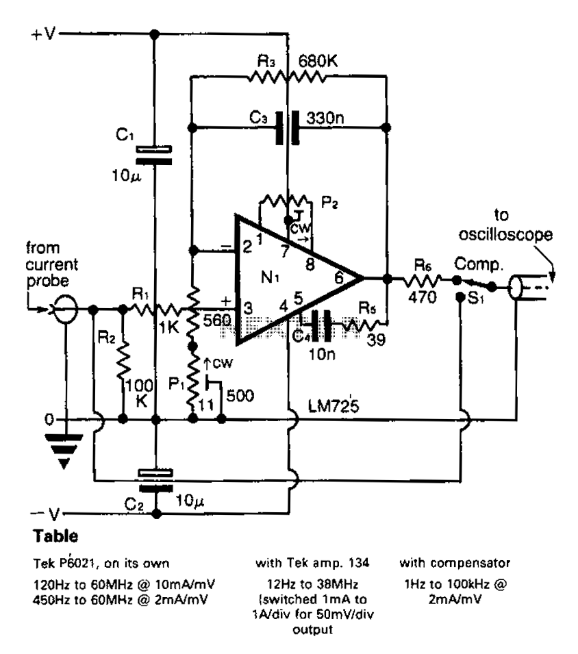
Description: A clip-on current probe, like the Tektronix P6021, is a valuable tool for displaying current waveforms on an oscilloscope. However, it has limitations in low-frequency response. Specifically, the P6021 is sensitive to a range of 2mA/mV, and frequencies below 450 Hz experience a roll-off of 6 dB per octave.
The Tektronix P6021 clip-on current probe is designed for non-invasive measurement of current waveforms in various electronic circuits. This probe allows for easy attachment to current-carrying conductors without the need for direct electrical contact, thereby minimizing disruption to the circuit under test. The probe operates effectively within a specific sensitivity range, which is critical for accurate measurements.
The sensitivity of 2mA/mV indicates that for every 2 mA of current flowing through the conductor, the output voltage will be 1 mV. This level of sensitivity is useful for capturing small current variations, making the P6021 ideal for applications involving low-level signals.
However, the performance of the P6021 is constrained at low frequencies. Below 450 Hz, the probe exhibits a roll-off of 6 dB per octave, which means that as frequency decreases, the output voltage decreases at a rate of 6 dB for every doubling of the frequency. This characteristic can lead to inaccuracies in measurements of low-frequency signals, as the probe may not effectively capture the full waveform, potentially resulting in distorted representations of the current.
In practical applications, users must be aware of these limitations when using the P6021 for low-frequency measurements. For optimal results, it is advisable to operate the probe within its specified frequency range and consider alternative measurement methods or equipment for low-frequency applications that require higher fidelity. Clip-on current probe, such as the Tektronix P6021 current waveform for oscilloscope display is very useful. Unfortunately, for the low-frequency response is always some limita tions, as follows: For P6021, sensitive to the range of 2mA/mV, when the frequencies below 450 Hz per octave rolloff 6dB.
The Tektronix P6021 clip-on current probe is designed for non-invasive measurement of current waveforms in various electronic circuits. This probe allows for easy attachment to current-carrying conductors without the need for direct electrical contact, thereby minimizing disruption to the circuit under test. The probe operates effectively within a specific sensitivity range, which is critical for accurate measurements.
The sensitivity of 2mA/mV indicates that for every 2 mA of current flowing through the conductor, the output voltage will be 1 mV. This level of sensitivity is useful for capturing small current variations, making the P6021 ideal for applications involving low-level signals.
However, the performance of the P6021 is constrained at low frequencies. Below 450 Hz, the probe exhibits a roll-off of 6 dB per octave, which means that as frequency decreases, the output voltage decreases at a rate of 6 dB for every doubling of the frequency. This characteristic can lead to inaccuracies in measurements of low-frequency signals, as the probe may not effectively capture the full waveform, potentially resulting in distorted representations of the current.
In practical applications, users must be aware of these limitations when using the P6021 for low-frequency measurements. For optimal results, it is advisable to operate the probe within its specified frequency range and consider alternative measurement methods or equipment for low-frequency applications that require higher fidelity. Clip-on current probe, such as the Tektronix P6021 current waveform for oscilloscope display is very useful. Unfortunately, for the low-frequency response is always some limita tions, as follows: For P6021, sensitive to the range of 2mA/mV, when the frequencies below 450 Hz per octave rolloff 6dB.
Spike Detector For Oscilloscopes
Dynamic flip-flops disregard input pulses that are shorter than 40 ns or do not conform to TTL voltage levels. Consequently, TTL flip-flops are not well-suited for certain applications.
Dynamic flip-flops are a specific type of sequential logic circuit that utilize dynamic...
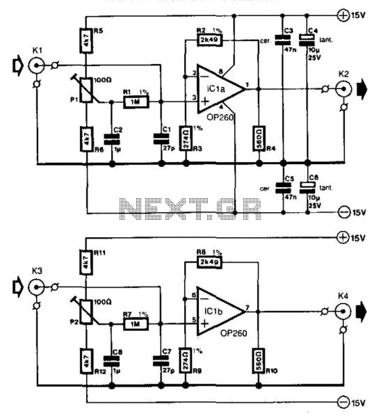
Oscilloscope Preamp
In many oscilloscopes, the most sensitive range is between 2 to 5 mV, although it is often possible to improve this to 1 to 2 mV by using a variable gain control. To achieve even better sensitivity, the current preamplifier,...
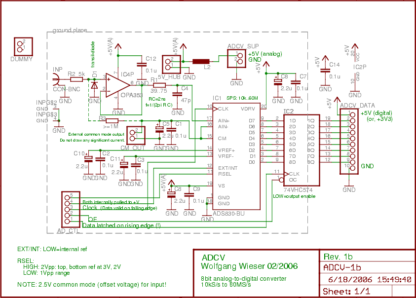
USB Live Oscilloscope: ADCV Board
The analog input is initially connected to a fast non-inverting buffer amplifier (OPA353) configured for unity gain, which safeguards the analog-to-digital converter from out-of-range voltages. The ADS830 is an economical 8-bit analog-to-digital converter that accommodates sampling clocks ranging from 10...
Spike Detector For Oscilloscopes
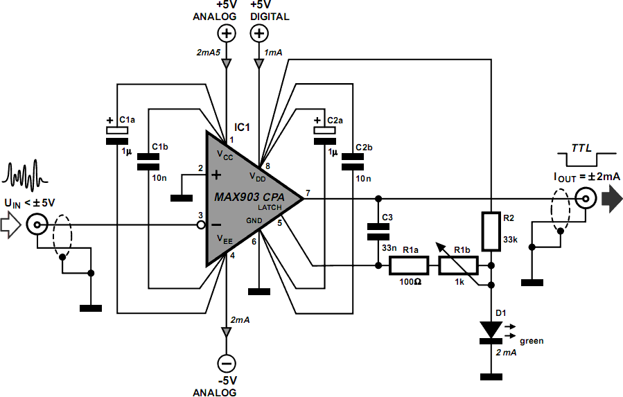
Dynamic flip-flops ignore pulses at their inputs that are shorter than 40 ns or do not have TTL levels. This means that TTL flip-flops are not well-suited for capturing noise pulses with unknown durations and magnitudes. This issue is commonly...
Component Signature for Oscilloscope
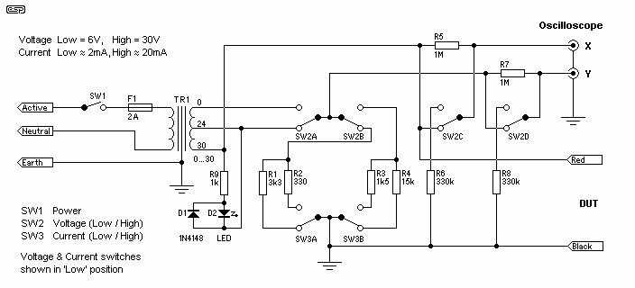
The general (and very basic) principle of operation is shown in Figure 1. The test signal is simply derived from the mains, and is a sinewave at 50 or 60Hz. In most locations, the sinewave will be distorted, but this...
Oscilloscope Xminilab-B on the microcontroller Atmel AVR ATXMEGA32A4
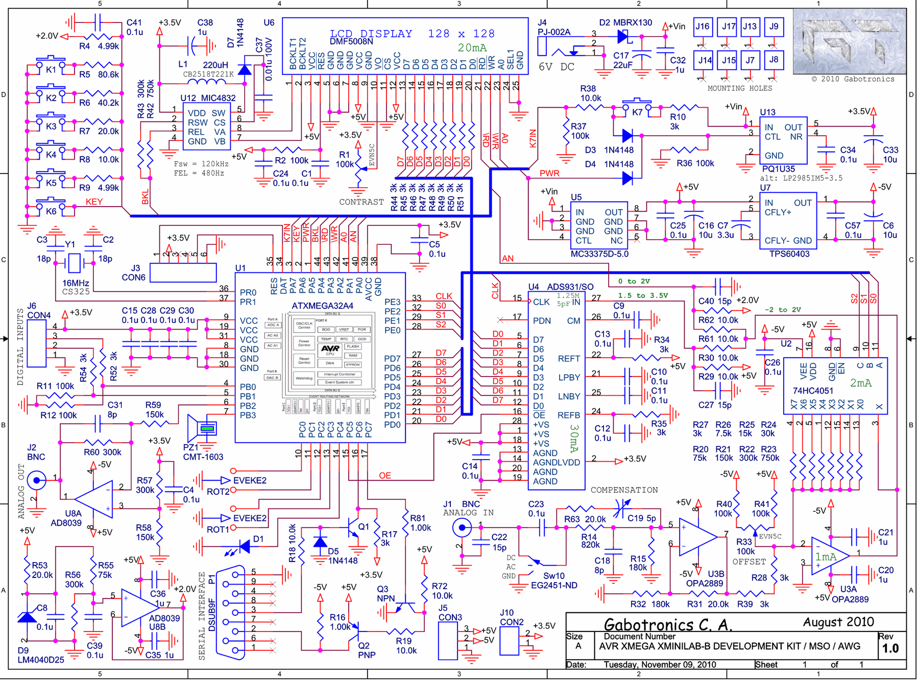
The Xminilab-B oscilloscope is based on the Atmel AVR ATXMEGA32A4 microcontroller. It is designed as a debug board by the Gabotronis company, as noted on rlocman.ru.
The Xminilab-B oscilloscope features a compact and efficient design that leverages the capabilities of the...
curve tracer adaptor schematics
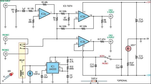
This unit utilizes a dual trace oscilloscope with X-Y functionality as a display to test and demonstrate the operation of circuits and components such as transistors, diodes, zener diodes, and both terminated and unterminated transformers. A low-frequency sine wave (e.g.,...
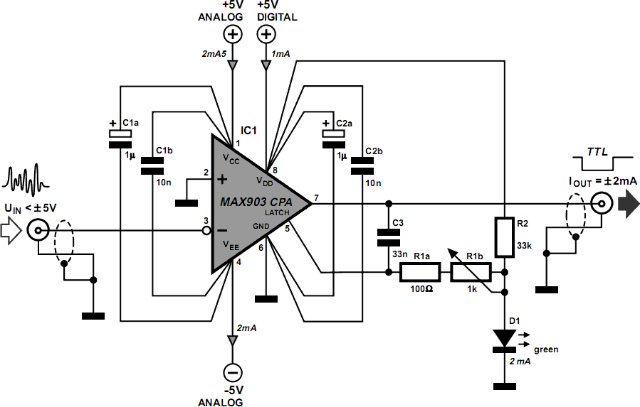
Spike Detector For Oscilloscopes
Dynamic flip-flops ignore pulses at their inputs that are shorter than 40 ns or do not have TTL levels. This limitation renders TTL flip-flops inadequate for capturing noise pulses with unknown durations and amplitudes. This issue is familiar to those...
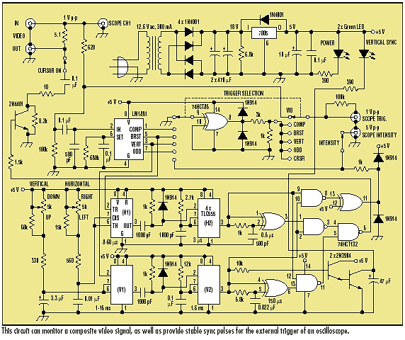
Video monitor adapter enhances oscilloscope
Video signals can be challenging to display on an oscilloscope. Standard trigger circuits in most oscilloscopes often struggle to achieve a stable trigger from the combined vertical and horizontal sync signals, color burst, and picture signal found in a composite...