


Computer AC power source monitoring circuit
#current transformer
#AC power
#power monitoring
#current sensing
#computer
#load detection
#power line
#sensor
#electronics
#instrumentation
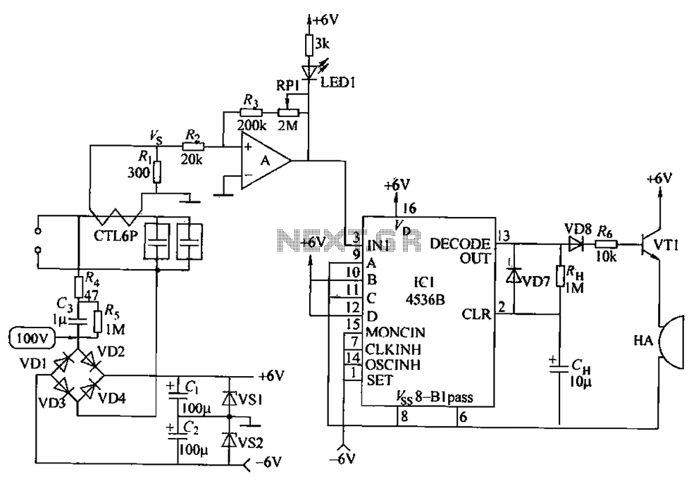
Description: The circuit principle involves using a current transformer for current sensing due to the large AC power load of computers. This setup detects whether there is current in the power line, enabling the determination of its status. The LM393 comparator circuit (A) is utilized, where an alarm time interval is established by IC1 once the power is turned on. When the input time (A, B, C, D) expires, a binary code is input, allowing for the setting of the IC1 time interval. Inputs B and D are set to a high level, while A and C are set to a low level. The input power frequency is divided by 1/2. If the power frequency is 50Hz, the output is triggered after approximately 87 minutes; if the frequency is 60Hz, it triggers after about 73 minutes. The output from the decoder (DECODE() UT) goes high, activating VT1, which drives a buzzer (HA) to sound. The duration of the sound is determined by RI-I and CH.
The circuit design incorporates a current transformer that senses the alternating current (AC) load typical in computer systems. This transformer is critical for monitoring the current flow in the power line, allowing for real-time status assessment. The LM393 comparator serves as a key component in this circuit, providing a means to compare voltage levels and generate an output based on the comparison results.
Upon powering the circuit, IC1 is responsible for setting the alarm time interval, which is crucial for the operation of the system. The circuit is designed to accept input signals labeled A, B, C, and D. The configuration of these inputs determines the operational state of the circuit. Specifically, when inputs B and D are high and A and C are low, the circuit is prepared to process the input time.
The circuit also features a frequency division mechanism that divides the input power frequency by two. This is particularly relevant when considering standard power frequencies of 50Hz or 60Hz, which are common in electrical systems worldwide. The timing calculations indicate that an output signal will be generated after approximately 87 minutes for a 50Hz input frequency and 73 minutes for a 60Hz input frequency.
The output from the decoder (DECODE() UT) becomes high at the end of the designated time interval, triggering the transistor VT1. This action activates the buzzer (HA), producing an audible alert. The duration of the buzzer sound is controlled by the resistor RI-I and capacitor CH, allowing for customization of the alarm duration based on user requirements or specific application needs. This comprehensive design facilitates effective monitoring and alerting in environments with significant power loads, enhancing operational safety and reliability. Circuit principle: computers AC power load is large, the use of the current transformer current sensing. It can be used to detect whether a current power line, determine its st atus. Schmitt is LM393 comparator circuit (A), after the power is turned on, set the alarm time interval by IC1 completed. When the input time (A, B, C, D) ended input binary code, 1C1 time interval can be set. B, D is set to the high level, A, and C is set to a low level. 1C1 input power frequency 1/2 division. If the power frequency is 50Hz, after about 87min, when power frequency is 60H, after about 73min, the output of the decoder (DECODE () UT) output high, VT1 conduction, HA buzzer sound, the sound of time from RI-I, CH decision.
The circuit design incorporates a current transformer that senses the alternating current (AC) load typical in computer systems. This transformer is critical for monitoring the current flow in the power line, allowing for real-time status assessment. The LM393 comparator serves as a key component in this circuit, providing a means to compare voltage levels and generate an output based on the comparison results.
Upon powering the circuit, IC1 is responsible for setting the alarm time interval, which is crucial for the operation of the system. The circuit is designed to accept input signals labeled A, B, C, and D. The configuration of these inputs determines the operational state of the circuit. Specifically, when inputs B and D are high and A and C are low, the circuit is prepared to process the input time.
The circuit also features a frequency division mechanism that divides the input power frequency by two. This is particularly relevant when considering standard power frequencies of 50Hz or 60Hz, which are common in electrical systems worldwide. The timing calculations indicate that an output signal will be generated after approximately 87 minutes for a 50Hz input frequency and 73 minutes for a 60Hz input frequency.
The output from the decoder (DECODE() UT) becomes high at the end of the designated time interval, triggering the transistor VT1. This action activates the buzzer (HA), producing an audible alert. The duration of the buzzer sound is controlled by the resistor RI-I and capacitor CH, allowing for customization of the alarm duration based on user requirements or specific application needs. This comprehensive design facilitates effective monitoring and alerting in environments with significant power loads, enhancing operational safety and reliability. Circuit principle: computers AC power load is large, the use of the current transformer current sensing. It can be used to detect whether a current power line, determine its st atus. Schmitt is LM393 comparator circuit (A), after the power is turned on, set the alarm time interval by IC1 completed. When the input time (A, B, C, D) ended input binary code, 1C1 time interval can be set. B, D is set to the high level, A, and C is set to a low level. 1C1 input power frequency 1/2 division. If the power frequency is 50Hz, after about 87min, when power frequency is 60H, after about 73min, the output of the decoder (DECODE () UT) output high, VT1 conduction, HA buzzer sound, the sound of time from RI-I, CH decision.
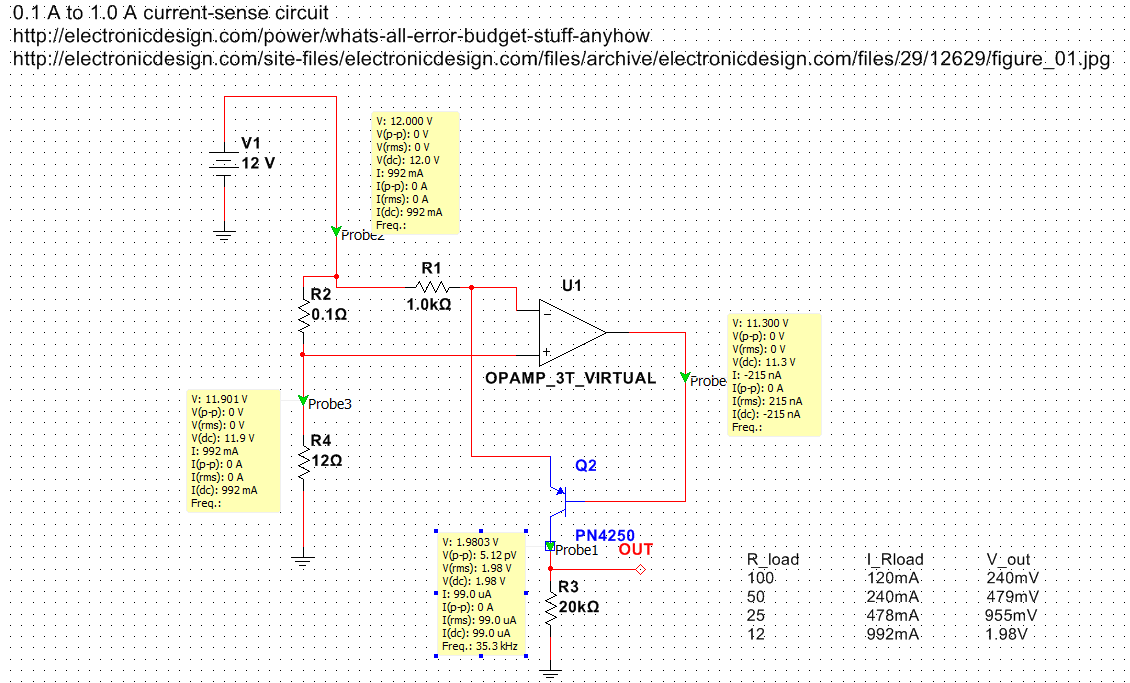
Current sense schematic question
Exploring various methods for current sensing using standard operational amplifiers instead of specialized chips like the MAX4073T/F/H, which perform well but are relatively expensive. An article by Bob Pease discussing "error budgets" caught attention, particularly Figure Two of the schematic,...
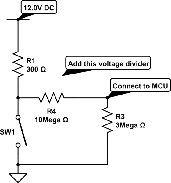
Is there a simpler solution for highside current sensing here
The loads consist of two or more solenoids connected in parallel, sharing a 12V supply. Each solenoid is individually switched to ground through the vehicle's ECU. The objective is to detect when any one of the circuits closes, ensuring that...
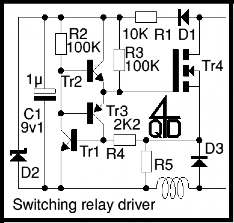
Current sensing relay
It operates by PWM (Pulse Width Modulation) - well, actually by PFM - Pulse Frequency Modulation. At power up, C1 charges up via D1 and R1. R2 will conduct, pulling the base of the emitter follower, Tr2, up and feeding...
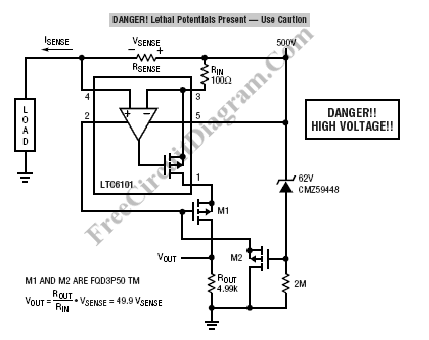
Current Sensing for High Voltage Application
High voltage current sensing and monitoring can be designed using the LTC6101 operational amplifier. The current sensing circuit outlined is capable of measuring electrical current.
The LTC6101 is a precision current sense amplifier designed to operate in high voltage environments, making...
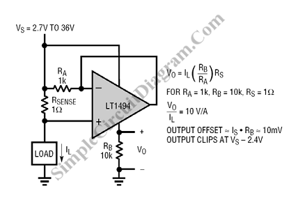
Self Powered Current Sensing
This is a current sensing circuit that measures the current on the high side, positioned between the load and the positive supply. This circuit takes advantage of...
A current sensing circuit serves a crucial role in monitoring the flow of electric...
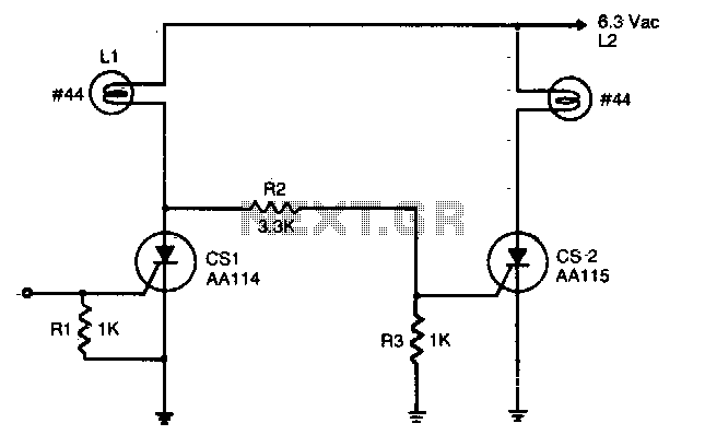
Complementary AC power switching
An input signal of less than 1 mA and 1V is required to switch on CS1. As long as this input signal is maintained, CS1 will conduct during each positive half-cycle of anode voltage, thereby energizing load L1 with half-wave...
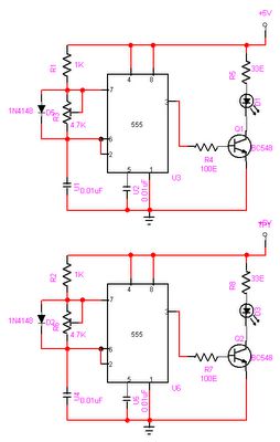
Automatic Room light Control With Bi Directional Visitor Counter
The objective of this project is to create a controller-based model that counts the number of individuals entering a specific room and activates the lighting accordingly. This is achieved through the use of sensors that detect the current number of...
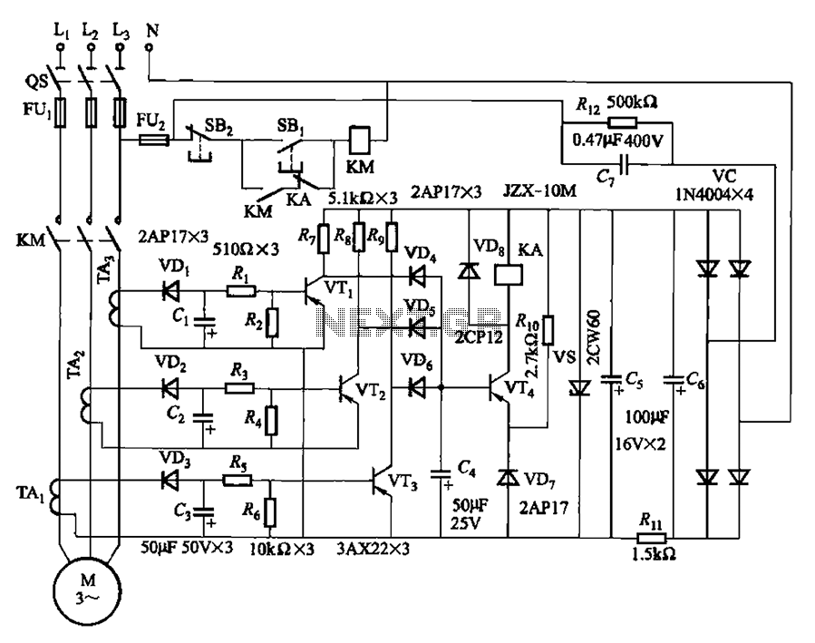
Detected line current Phase protective circuit 2
The current detection signal is obtained from three current transformers after rectification and filtering, resulting in three DC voltage outputs. These voltages are applied to transistors VT1, VT2, and VTa between the base and emitter. The signal is amplified by...
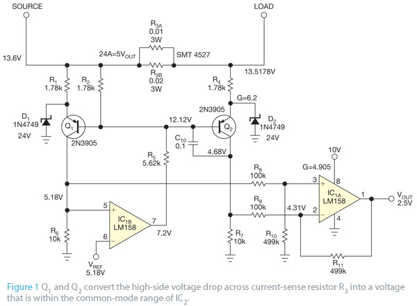
Sense automobile high-side current with discrete components
This design concept originated from the lack of access to advanced integrated circuits (ICs) that are capable of sensing current. A discrete circuit was required that could be easily constructed while still maintaining accuracy comparable to that of modern ICs....