


DC RMS And Peak-to-Peak High Impedance Voltmeter
#voltmeter
#high impedance
#analog meter
#buffer circuit
#RMS measurement
#peak-to-peak measurement
#active buffering
#input impedance
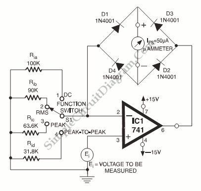
Description: An analog meter typically does not exhibit high impedance due to the absence of a buffer circuit within its design. By incorporating active buffering, the input impedance of this circuit can be significantly enhanced.
The integration of an active buffer circuit into an analog meter serves to improve its input impedance, which is crucial for accurate measurement in various electronic applications. A buffer circuit, often implemented using operational amplifiers (op-amps), isolates the meter from the circuit being tested. This isolation minimizes the loading effect that the meter might impose on the circuit, thereby preventing distortion of the measured signal.
In practical terms, an operational amplifier configured as a voltage follower can be used as an active buffer. The non-inverting input of the op-amp is connected to the signal source, while the output is connected to the analog meter. This configuration allows the op-amp to provide a high input impedance, typically in the range of megaohms, while maintaining a low output impedance. Consequently, the analog meter can accurately reflect the voltage of the source without drawing significant current from it.
The benefits of this approach are particularly evident in high-impedance applications, such as measuring signals from sensors or other sensitive devices. The active buffer circuit ensures that the analog meter can operate effectively without influencing the source signal, thus providing more reliable and precise readings. Additionally, the use of active buffering can enhance the frequency response of the measurement system, allowing for the detection of rapid signal changes that might otherwise be missed with a traditional analog meter.
In conclusion, incorporating an active buffer circuit into an analog meter design not only enhances its input impedance but also significantly improves measurement accuracy and reliability across a range of electronic applications.Analog meter normally doesn`t have high impedance since they don`t have buffer circuit inside. With active buffering, the input impedance of this circuit..
The integration of an active buffer circuit into an analog meter serves to improve its input impedance, which is crucial for accurate measurement in various electronic applications. A buffer circuit, often implemented using operational amplifiers (op-amps), isolates the meter from the circuit being tested. This isolation minimizes the loading effect that the meter might impose on the circuit, thereby preventing distortion of the measured signal.
In practical terms, an operational amplifier configured as a voltage follower can be used as an active buffer. The non-inverting input of the op-amp is connected to the signal source, while the output is connected to the analog meter. This configuration allows the op-amp to provide a high input impedance, typically in the range of megaohms, while maintaining a low output impedance. Consequently, the analog meter can accurately reflect the voltage of the source without drawing significant current from it.
The benefits of this approach are particularly evident in high-impedance applications, such as measuring signals from sensors or other sensitive devices. The active buffer circuit ensures that the analog meter can operate effectively without influencing the source signal, thus providing more reliable and precise readings. Additionally, the use of active buffering can enhance the frequency response of the measurement system, allowing for the detection of rapid signal changes that might otherwise be missed with a traditional analog meter.
In conclusion, incorporating an active buffer circuit into an analog meter design not only enhances its input impedance but also significantly improves measurement accuracy and reliability across a range of electronic applications.Analog meter normally doesn`t have high impedance since they don`t have buffer circuit inside. With active buffering, the input impedance of this circuit..
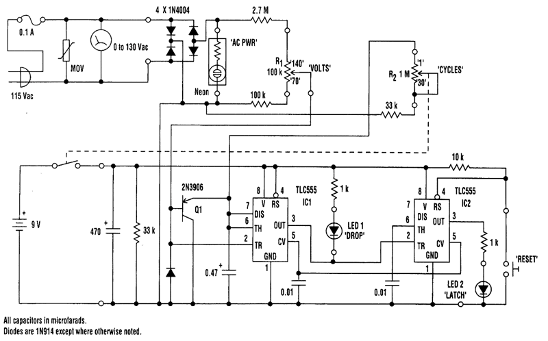
ac POWER MONITOR
The 0 to 130-volt voltmeter and neon "AC PWR" lamp provide an average indication of AC power. The fuse and metal oxide varistor (MOV) protect the monitor against overvoltage spikes. Four 1N4004 diodes rectify the AC voltage, generating negative-going pulses...
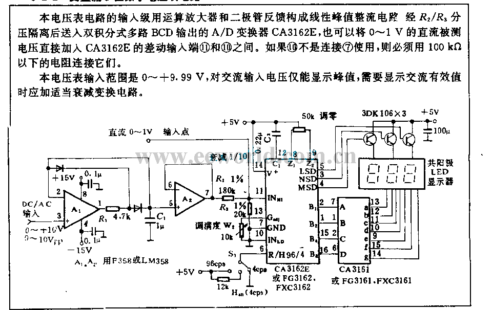
AC/DC 3 digits voltmeter circuit
The input stage of this voltmeter circuit utilizes an operational amplifier and diode feedback to create a linear peak value rectifier circuit. A partial pressure isolation through resistors R1 and R2 directs the signal to a dual multi-channel BCD output...
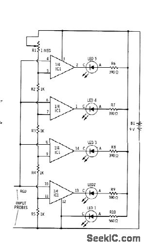
BAR GRAPH READOUT VOLTMETER
Sections of the RS339 quad comparator each drive an LED to indicate four different input voltage levels. LED 1 is connected to ground to serve as a zero indicator. The resistors depicted are intended for Radio Shack 276-041 red LEDs;...
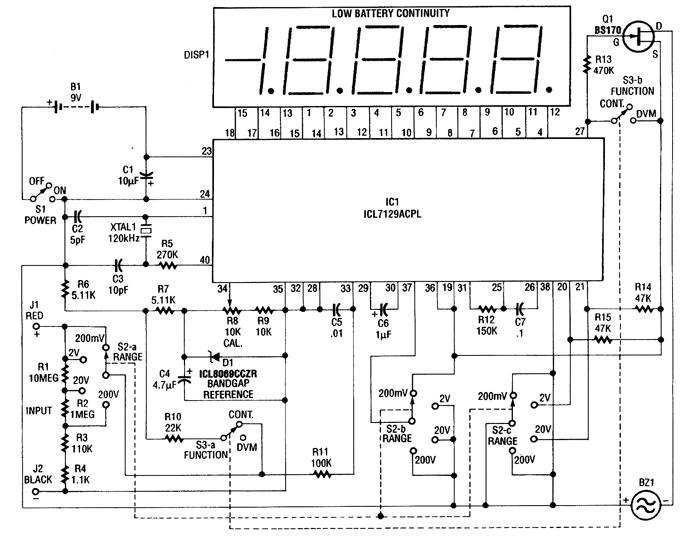
SINGLE CHIP DIGITAL VOLTMETER
This 4.5-digit digital voltmeter (DVM) circuit is designed around the Maxim ICL7129ACPL analog-to-digital converter (A/D converter) and an LCD driver. It utilizes an ICL8069 CCZR 1.2-V band-gap reference diode for voltage referencing. The switch S2a-b-c allows the selection of one...
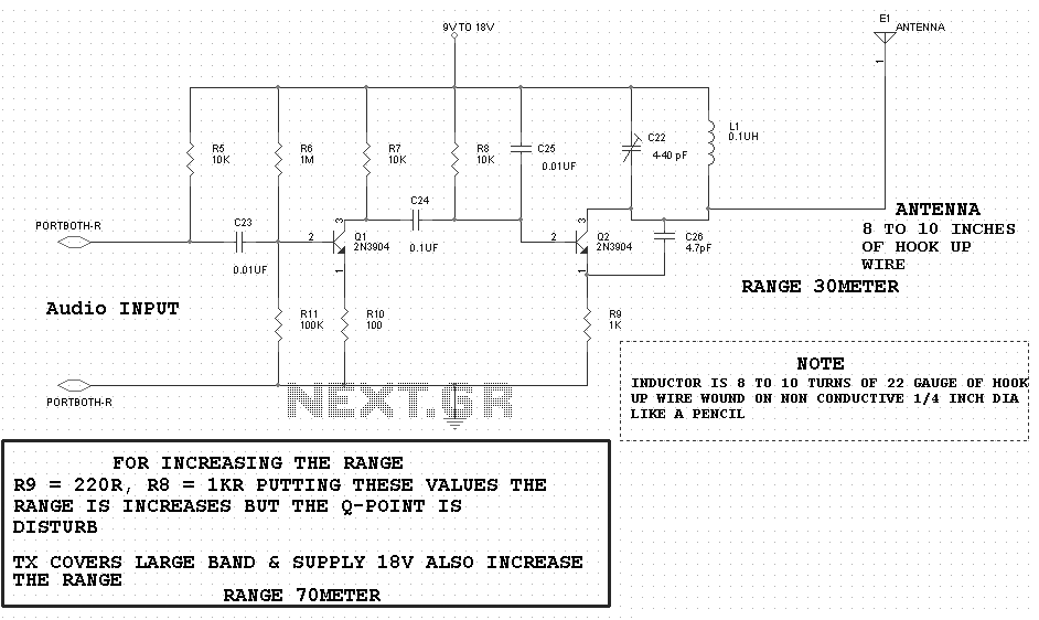
Tonal Electrostatic Voltmeter Device
A highly effective method for providing continuous and direct indication of electrostatic voltmeter (ESV) readings, even in large lecture halls, is to integrate this instrument with a tonal voltmeter (TVM). The TVM emits an audible tone of constant amplitude, with...
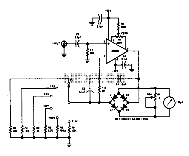
Wide band AC voltmeter
This voltmeter is capable of measuring AC signals as low as 15 mV at frequencies from 100 Hz to 500 kHz. Full-scale sensitivity may be changed by altering the values of R1 through R6 (R = Vin/100 µA).
The described voltmeter...
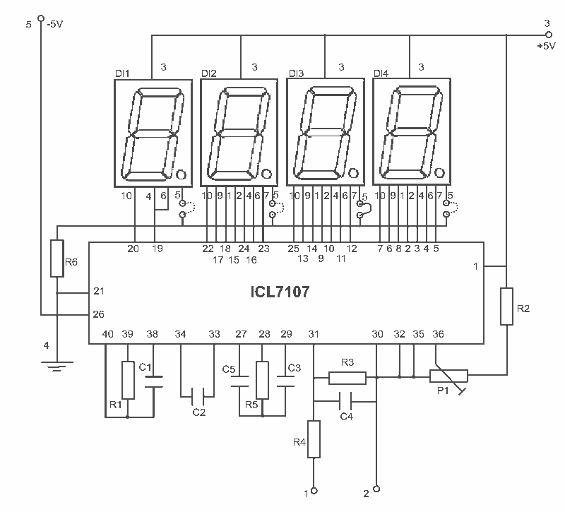
LED digital Voltmeter
This is an easy to build, but nevertheless very accurate and useful digital voltmeter. It has been designed as a panel meter and can be used in DC power supplies or anywhere else it is necessary to have an accurate...
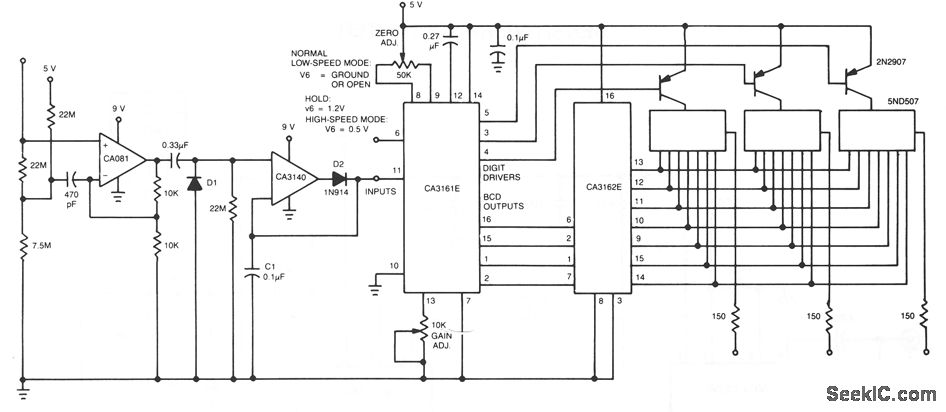
AC VOLTMETER
The CA081 and CA3140 BiMOS operational amplifiers provide minimal loading on the circuits being measured. The wide bandwidth and high slew rate of the CA081 enable the meter to operate at frequencies up to 0.5 MHz.
The CA081 and CA3140 are...

converter voltmeter to frequency meter
This design circuit is for converting voltage to frequency. Typically, frequency meters are used in speed sensors, tachometers, and for measuring recurring signals. The frequency to voltage converter (FVC) can transform voltage into either a digital or analog tachometer. The...