


decibel meter circuit
#decibel meter
#VU meter
#audio signal
#LED display
#sound measurement
#audio system
#signal strength
#hifi
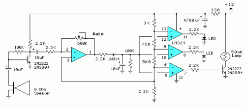
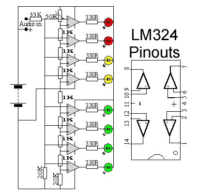
Description: The series of decibel meters functions to determine the signal strength level delivered to the speakers in an audio system. This decibel meter circuit is commonly referred to as VU meters in high-fidelity audio systems. The series of decibel meters discussed in this article showcases advanced techniques with signal lights and LEDs. The input circuit for the decibel meter is derived from the audio system's output, which connects to the speakers. This series employs an LM324 integrated circuit as a comparator and a single-level amplifier with gain control. The construction of the decibel meter or VU meter is relatively straightforward, and the circuit details can be observed in the accompanying figure. The series requires a 12V DC voltage source and an input signal from the audio power output connected to the speakers. These decibel meters can be installed in powered speakers or other audio amplifier systems. The sensitivity of the audio signal reception can be adjusted by modifying the value of VR500K, which acts as a feedback and reinforcement factor, influencing the amplifier circuit preceding the decibel meter.
The decibel meter circuit, or VU meter, is a valuable tool in audio systems for visualizing signal strength. This circuit typically utilizes an LM324 operational amplifier, which serves dual purposes: as a comparator to assess the input signal level and as an amplifier to enhance the signal for accurate representation. The circuit design allows for the integration of multiple LED indicators that light up in response to varying signal levels, providing a clear visual cue of audio intensity.
The input stage of the circuit is connected directly to the output of the audio amplifier, ensuring that the decibel meter accurately reflects the audio signal being sent to the speakers. The circuit is powered by a 12V DC supply, which is standard for many audio applications. The use of a variable resistor, VR500K, is critical for tuning the sensitivity of the meter. By adjusting this resistor, users can calibrate the circuit to respond appropriately to different signal levels, ensuring that the meter provides a meaningful representation of audio output without distortion or clipping.
Furthermore, the design can be adapted for various applications, such as in powered speakers or standalone audio amplifier systems. The simplicity of the circuit allows for easy assembly and integration into existing audio setups, making it an ideal project for both hobbyists and professional audio engineers. The visual feedback provided by the decibel meter enhances the user experience, allowing for real-time monitoring of audio levels and ensuring optimal performance of the audio system.The series of decibel meter function to determine the level of signal strength that is given to the speaker on the audio system. Decibel meter circuit is often also known as the VU meters on audio hifi system. For a series of decibel meters in this article displays strong technique with signal lights and LED. Decibel meter input circuit is taken f rom the output of the audio system that will connect to the speakers. The series uses a decibel meter this fruit as a comparator LM324 IC and 1 level amplifier with gain control. The series of decibel meter or VU meter is quite simple to make and circuit details can be seen in the following figure.
The series of decibel meters above requires 12VDC voltage source and an input signal from the audio power output that is connected to the speakers. The series of decibel meters can be installed on powered speakers or other audio amplifier system. To adjust the audio signal reception sensitivity is set by adjusting the value VR500K which serves as feedback and reinforcement factors will affect the amplifier circuit ahead of the decibel meter.
The decibel meter circuit, or VU meter, is a valuable tool in audio systems for visualizing signal strength. This circuit typically utilizes an LM324 operational amplifier, which serves dual purposes: as a comparator to assess the input signal level and as an amplifier to enhance the signal for accurate representation. The circuit design allows for the integration of multiple LED indicators that light up in response to varying signal levels, providing a clear visual cue of audio intensity.
The input stage of the circuit is connected directly to the output of the audio amplifier, ensuring that the decibel meter accurately reflects the audio signal being sent to the speakers. The circuit is powered by a 12V DC supply, which is standard for many audio applications. The use of a variable resistor, VR500K, is critical for tuning the sensitivity of the meter. By adjusting this resistor, users can calibrate the circuit to respond appropriately to different signal levels, ensuring that the meter provides a meaningful representation of audio output without distortion or clipping.
Furthermore, the design can be adapted for various applications, such as in powered speakers or standalone audio amplifier systems. The simplicity of the circuit allows for easy assembly and integration into existing audio setups, making it an ideal project for both hobbyists and professional audio engineers. The visual feedback provided by the decibel meter enhances the user experience, allowing for real-time monitoring of audio levels and ensuring optimal performance of the audio system.The series of decibel meter function to determine the level of signal strength that is given to the speaker on the audio system. Decibel meter circuit is often also known as the VU meters on audio hifi system. For a series of decibel meters in this article displays strong technique with signal lights and LED. Decibel meter input circuit is taken f rom the output of the audio system that will connect to the speakers. The series uses a decibel meter this fruit as a comparator LM324 IC and 1 level amplifier with gain control. The series of decibel meter or VU meter is quite simple to make and circuit details can be seen in the following figure.
The series of decibel meters above requires 12VDC voltage source and an input signal from the audio power output that is connected to the speakers. The series of decibel meters can be installed on powered speakers or other audio amplifier system. To adjust the audio signal reception sensitivity is set by adjusting the value VR500K which serves as feedback and reinforcement factors will affect the amplifier circuit ahead of the decibel meter.
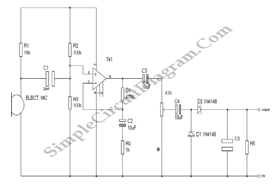
Audio Signal Strength Detector/Converter
Below is the schematic diagram of an audio input module. This module is capable of producing a DC output voltage that is proportional to the amplitude of the input signal.
The audio input module typically consists of several key components that...
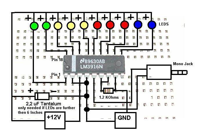
Case Modification - Stereo VU Meter
This is a concise guide for constructing a stereo VU meter utilizing the LM3915/LM3916 integrated circuits. The LM3916 is designed to convert analog voltage levels into visual representations through the activation of 10 LEDs, LCDs, or vacuum fluorescent displays, similar...
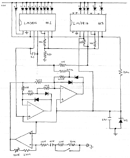
Electronic VU Meter
A portable CD player, radio, cassette player, a couple of microphones, and a PC sound card are connected to the inputs of an audio mixer. The output of the mixer is connected to a pair of active loudspeakers. The objective...
Common-cathode-led-display
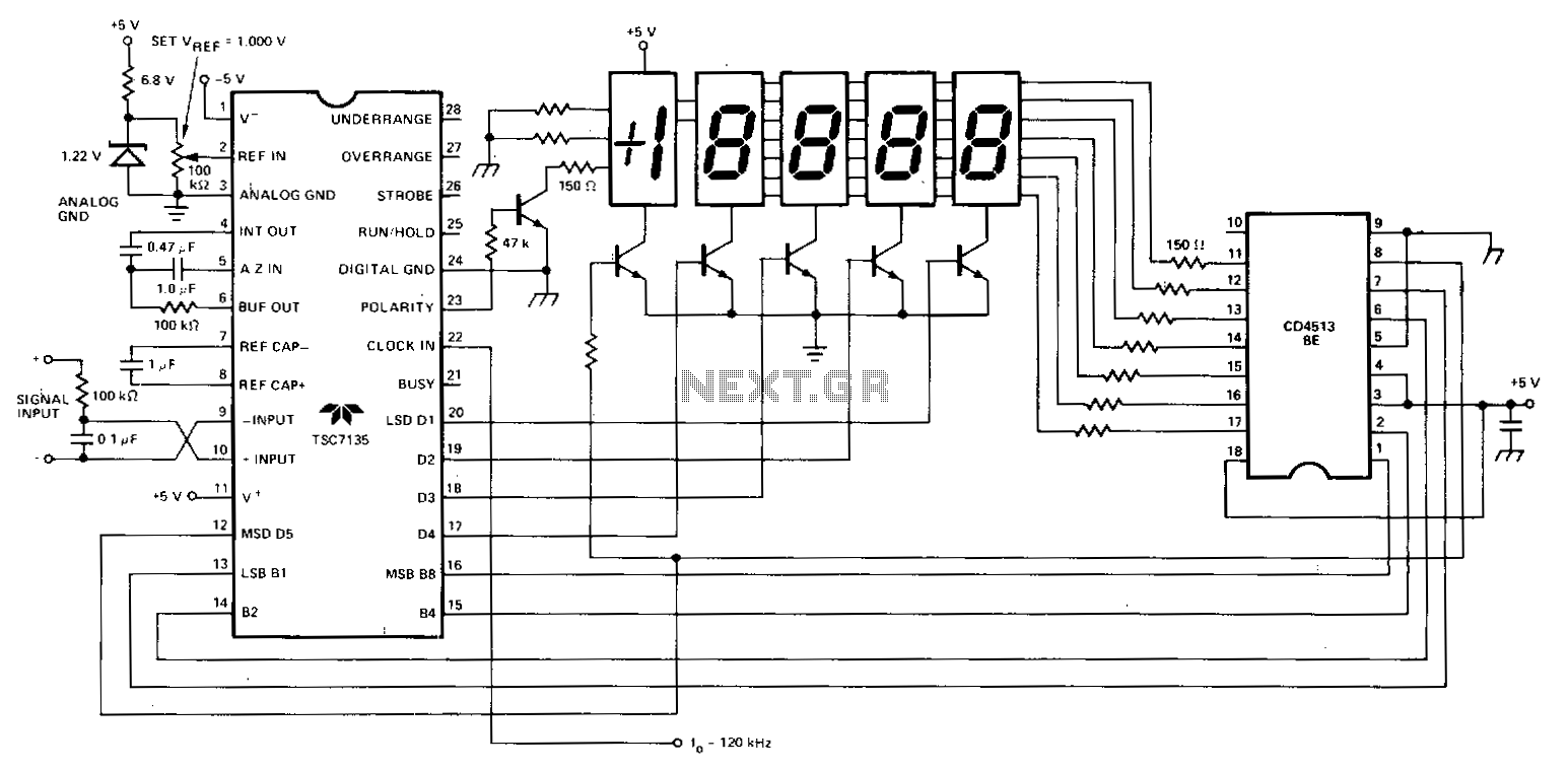
A Teledyne TSC7135 digital voltmeter (DVM) chip is utilized to control a multiplexed 5-digit display. To facilitate common cathode drive, a CD4513BE CMOS integrated circuit (IC) functions as a segment driver, with selection controlled by pins 17-20 of the DVM...
Audio VU Level Meter Circuit with LM324
This weblog discusses electronic circuit schematics, PCB design, DIY kits, and electronic project diagrams. The 1K resistors in the circuit are significant as they allow the LEDs to activate at different audio levels. While these resistors can be modified, using...
Roulette with LED Display
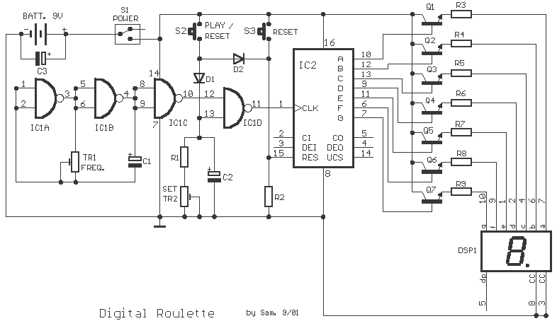
This circuit is a small digital roulette. It is constituted by oscillator IC1, the counter IC2, the transistors Q1-7 that drive the display common cathode DSP1. The supply basically becomes from a battery 9V, but can become also from one...
HiFi expandor with De-emphasis
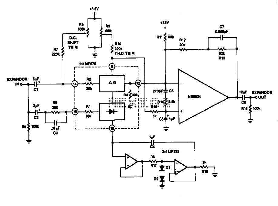
It can reduce its gain. The time it takes for the compressor to recover from overload is determined by the rectifier. The expander, such as a capacitor, completes the compressor as shown in FIG. 2-13B. An external operational amplifier is...
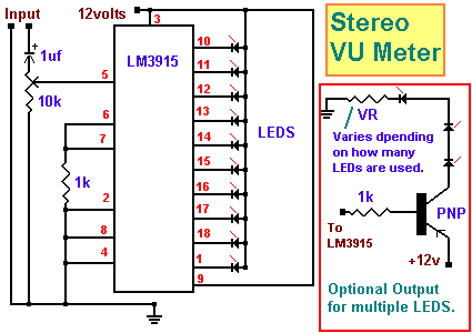
Simple Stereo VU Meter
This project indicates the audio volume level going to speakers by illuminating LEDs. The LEDs can be of any color, allowing for creative combinations. The circuit input is connected to the speaker output of an audio amplifier. Two identical units...
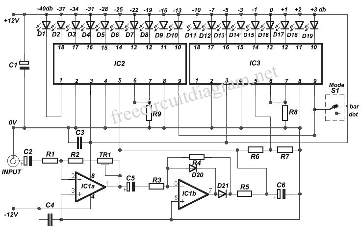
VU Meter using LM3915
This is a circuit schematic diagram for VU meters. The circuit is controlled by the IC TL072 and follows a measurement circuit as per the National general application. The input circuit around IC1 is designed for adaptation and amplification using...