


Decibel-o-meter and white noise generator
#decibel meter
#white noise generator
#audio amplifier
#noise measurement
#vintage receivers
#bandlimiting circuit
#Zener diode
#MPS918
#LA7MI
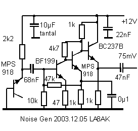
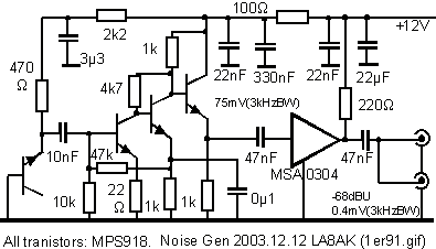
Description: Noise level measured into 75ohm 3.1kHz BW using Siemens D2006 level meter: -80dBU (77.5mV) from zero to 1MHz and drops 3dB on 17MHz. Decrease the first coupling capacitor (68nF) to 10nF to increase the lower limit to 50kHz. The amplifier is copied from one of LA7MI's constructions, combined with a general audio amplifier. A noise level was needed to test vintage receivers and requirement was not beyond 10MHz, but it seems that some further bandlimiting circuit could well be used, particularly since I am not interested in noise spectre below 200kHz. Picture: Zenerdiode connected (E-B junction) MPS918 at left side and the other devices follow as on the circuit diagram. The component values were first calculated, but I used the components which was closest, but it seems to cause no problem because of the heavy DC feedback. Reducing first emitter resistor (from 47 to 22W) to the half value will increases the output by 3dB on the lowest frequencies. More: The 2nd version built on tinned iron plate, output is measured using Siemens D2006 selective level meter to -66dBU 75W (3.1kHz BW), and 30mV into 50W using LA7MI broadband voltmeter (described further down this page). Suppose this is quite high level and I am not sure if it is worth increasing it further since the main task is to check surplus receivers. Level on 10MHz has dropped by 2dB. The noise generators were housed in NERA surplus boxes, and the 2nd room is not used. Have kept the conhex connectors since they are free and available in very large quantities as well as different cablelengths with connectors. It is some some minor changes of components for the two different versions. It increases the gain by 3dB, without any noticable change of frequency response, but the only measurable difference is that the version has 3dB, so it seems no problem to copy the circuits, the only importance is to choose a device with 6v e-b breakdown voltage. The box measures 100x80x30mm. White Noise generator with MSA0304 booster amplifier. The picture shows the 1st version noise generator which has -68dBU 75 ohm o/p (3.1kHz BW), while the 2nd has -66dBU.
The circuit described is a noise generator designed to test vintage receivers, optimized for a bandwidth of 3.1 kHz and a characteristic output impedance of 75 ohms. The noise level was measured using a Siemens D2006 level meter, which indicated a noise floor of -80 dBU (equivalent to 77.5 mV) from DC to 1 MHz, with a noted drop of 3 dB at 17 MHz. To enhance the lower frequency limit to 50 kHz, the first coupling capacitor, originally rated at 68 nF, should be reduced to 10 nF.
The amplifier design is derived from a construction by LA7MI, integrated with a general audio amplifier configuration. This design choice ensures adequate noise levels for testing purposes without exceeding the 10 MHz limit. It is suggested that a bandlimiting circuit may be beneficial, as the noise spectrum below 200 kHz is not of interest for the intended application.
The schematic includes a Zener diode connected at the emitter-base junction of an MPS918 transistor, positioned on the left side of the circuit. The components were selected based on availability, with slight variations from the originally calculated values. Despite these changes, the robust DC feedback mechanism allows for stable performance without significant issues. A modification to the first emitter resistor, reducing its value from 47 ohms to 22 ohms, results in a 3 dB increase in output at lower frequencies.
The second version of the noise generator is constructed on a tinned iron plate. Output measurements taken with the Siemens D2006 level meter indicate a noise level of -66 dBU at 75 ohms (3.1 kHz bandwidth) and 30 mV into a 50-ohm load, as verified by an LA7MI broadband voltmeter. While this output level is considered sufficient for the primary task of evaluating surplus receivers, a 2 dB reduction in output is observed at 10 MHz.
The noise generators are housed in surplus NERA boxes, with the use of conhex connectors noted for their availability in various lengths. Minor component changes are implemented between the two versions, resulting in a consistent 3 dB gain increase without affecting the frequency response. The only critical requirement is to select a device with a 6V emitter-base breakdown voltage. The overall dimensions of the housing are 100 mm x 80 mm x 30 mm, accommodating a white noise generator paired with an MSA0304 booster amplifier. The first version of the noise generator achieves an output of -68 dBU at 75 ohms, while the second version improves this to -66 dBU.Noise level measured into 75ohm 3.1kHz BW using Siemens D2006 level meter: -80dBU (77.5mV) from zero to 1MHz and drops 3dB on 17MHz. Decrease the first coupling capacitor (68nF) to 10nF to increase the lower limit to 50kHz. The amplifier is copied from one of LA7MI's constructions, combined with a general audio amplifier.
A noise level was needed to test vintage receivers and requirement was not beyond 10MHz, but it seems that some further bandlimiting circuit could well be used, particularly since I am not interested in noise spectre below 200kHz. Picture: Zenerdiode connected (E-B junction) MPS918 at left side and the other devices follow as on the circuit diagram.
The component values were first calculated, but I used the components which was closest, but it seems to cause no problem because of the heavy DC feedback. Reducing first emitter resistor (from 47 to 22W) to the half value will increases the output by 3dB on the lowest frequencies.
The 2nd version built on tinned iron plate, output is measured using Siemens D2006 selective level meter to -66dBU 75W (3.1kHz BW), and 30mV into 50W using LA7MI broadband voltmeter (described further down this page). Suppose this is quite high level and I am not sure if it is worth increasing it further since the main task is to check surplus receivers.
Level on 10MHz has dropped by 2dB. The noise generators were housed in NERA surplus boxes, and the 2nd room is not used. Have kept the conhex connectors since they are free and available in very large quantities as well as different cablelengths with connectors. It is some some minor changes of components for the two different versions. It increases the gain by 3dB, without any noticable change of frequency response, but the only measurable difference is that the version has 3dB, so it seems no problem to copy the circuits, the only importance is to choose a device with 6v e-b breakdown voltage.
The box measures 100x80x30mm. White Noise generator with MSA0304 booster amplifier. The picture shows the 1st version noise generator which has -68dBU 75 ohm o/p (3.1kHz BW), while the 2nd has -66dBU
The circuit described is a noise generator designed to test vintage receivers, optimized for a bandwidth of 3.1 kHz and a characteristic output impedance of 75 ohms. The noise level was measured using a Siemens D2006 level meter, which indicated a noise floor of -80 dBU (equivalent to 77.5 mV) from DC to 1 MHz, with a noted drop of 3 dB at 17 MHz. To enhance the lower frequency limit to 50 kHz, the first coupling capacitor, originally rated at 68 nF, should be reduced to 10 nF.
The amplifier design is derived from a construction by LA7MI, integrated with a general audio amplifier configuration. This design choice ensures adequate noise levels for testing purposes without exceeding the 10 MHz limit. It is suggested that a bandlimiting circuit may be beneficial, as the noise spectrum below 200 kHz is not of interest for the intended application.
The schematic includes a Zener diode connected at the emitter-base junction of an MPS918 transistor, positioned on the left side of the circuit. The components were selected based on availability, with slight variations from the originally calculated values. Despite these changes, the robust DC feedback mechanism allows for stable performance without significant issues. A modification to the first emitter resistor, reducing its value from 47 ohms to 22 ohms, results in a 3 dB increase in output at lower frequencies.
The second version of the noise generator is constructed on a tinned iron plate. Output measurements taken with the Siemens D2006 level meter indicate a noise level of -66 dBU at 75 ohms (3.1 kHz bandwidth) and 30 mV into a 50-ohm load, as verified by an LA7MI broadband voltmeter. While this output level is considered sufficient for the primary task of evaluating surplus receivers, a 2 dB reduction in output is observed at 10 MHz.
The noise generators are housed in surplus NERA boxes, with the use of conhex connectors noted for their availability in various lengths. Minor component changes are implemented between the two versions, resulting in a consistent 3 dB gain increase without affecting the frequency response. The only critical requirement is to select a device with a 6V emitter-base breakdown voltage. The overall dimensions of the housing are 100 mm x 80 mm x 30 mm, accommodating a white noise generator paired with an MSA0304 booster amplifier. The first version of the noise generator achieves an output of -68 dBU at 75 ohms, while the second version improves this to -66 dBU.Noise level measured into 75ohm 3.1kHz BW using Siemens D2006 level meter: -80dBU (77.5mV) from zero to 1MHz and drops 3dB on 17MHz. Decrease the first coupling capacitor (68nF) to 10nF to increase the lower limit to 50kHz. The amplifier is copied from one of LA7MI's constructions, combined with a general audio amplifier.
A noise level was needed to test vintage receivers and requirement was not beyond 10MHz, but it seems that some further bandlimiting circuit could well be used, particularly since I am not interested in noise spectre below 200kHz. Picture: Zenerdiode connected (E-B junction) MPS918 at left side and the other devices follow as on the circuit diagram.
The component values were first calculated, but I used the components which was closest, but it seems to cause no problem because of the heavy DC feedback. Reducing first emitter resistor (from 47 to 22W) to the half value will increases the output by 3dB on the lowest frequencies.
The 2nd version built on tinned iron plate, output is measured using Siemens D2006 selective level meter to -66dBU 75W (3.1kHz BW), and 30mV into 50W using LA7MI broadband voltmeter (described further down this page). Suppose this is quite high level and I am not sure if it is worth increasing it further since the main task is to check surplus receivers.
Level on 10MHz has dropped by 2dB. The noise generators were housed in NERA surplus boxes, and the 2nd room is not used. Have kept the conhex connectors since they are free and available in very large quantities as well as different cablelengths with connectors. It is some some minor changes of components for the two different versions. It increases the gain by 3dB, without any noticable change of frequency response, but the only measurable difference is that the version has 3dB, so it seems no problem to copy the circuits, the only importance is to choose a device with 6v e-b breakdown voltage.
The box measures 100x80x30mm. White Noise generator with MSA0304 booster amplifier. The picture shows the 1st version noise generator which has -68dBU 75 ohm o/p (3.1kHz BW), while the 2nd has -66dBU
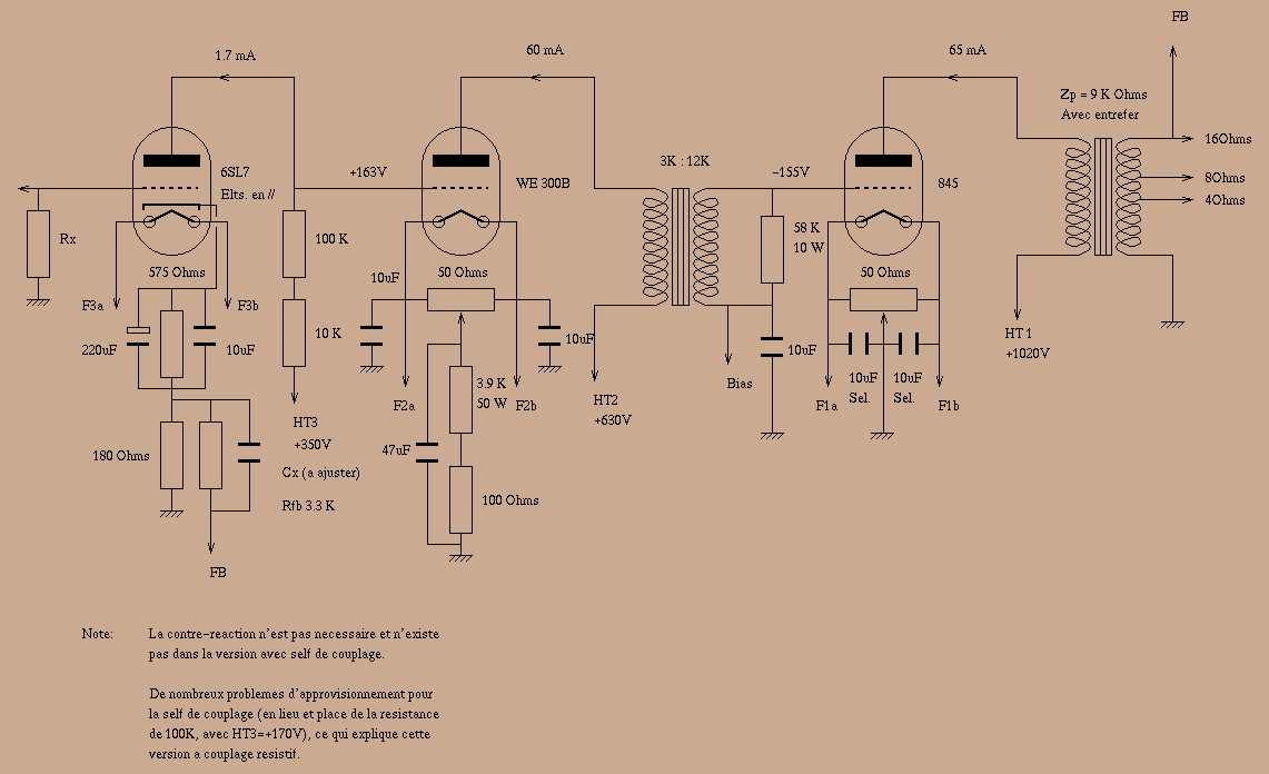
845 20W A1 class monotriode amplifier
This project is finalized, that means it is no longer experimental. This amplifier, although limited in output power (20W), has been designed to give the best listening pleasure. No compromise has been made during components choice: the 845 output triode...
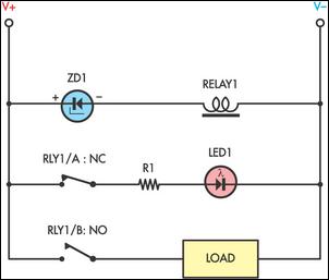
Simple Under-Voltage Cut-Out
Sensitive low-current relay coils often operate at much lower voltages than their typical ratings. This can be undesirable in some applications, where low supply voltages can result in erratic system behavior. In some instances, this problem could be overcome simply...
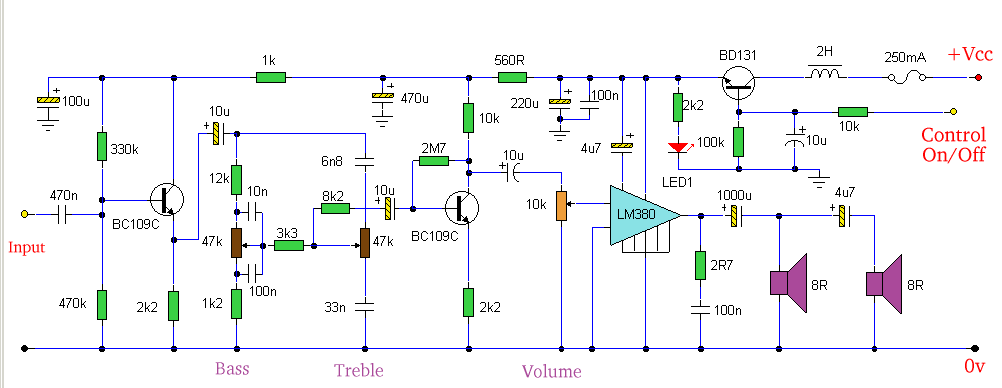
Amp with Tone Controls & Soft Switching
Amplifier with tone controls and soft switching. Notes: The soft switching is enabled by a BD131 transistor configured as a switch in an emitter follower arrangement. The collector is connected to a permanent load.
The described amplifier circuit incorporates tone controls...
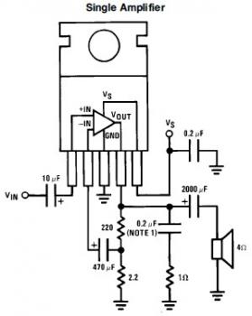
7W Mini Audio Amplifier Circuit based LM383
This is a simple mini audio amplifier circuit built around a single LM383 integrated circuit, along with several discrete components to support its operation. The circuit is capable of delivering approximately 7W of audio output. It can be constructed on...
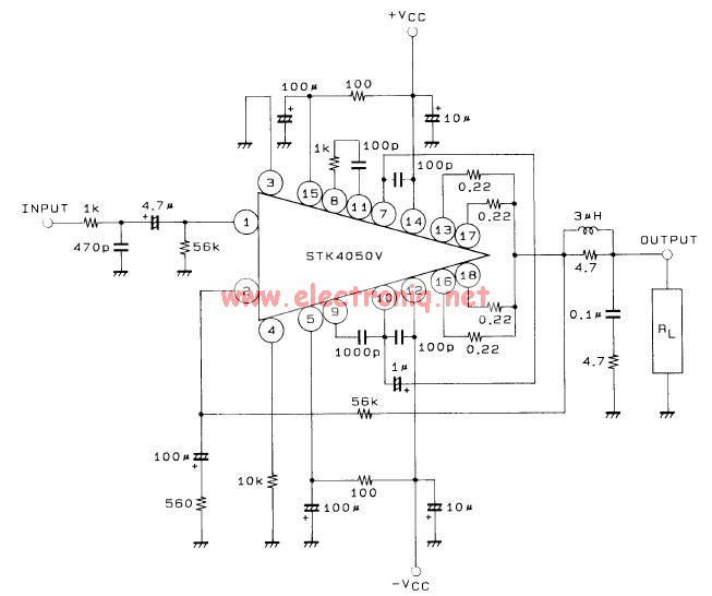
STK4050V audio amplifier circuit
This 200-watt audio amplifier circuit diagram is based on the STK4050V high-power audio amplifier IC, designed to deliver up to 200 watts of audio power on a single channel. The STK4050V 200-watt audio amplifier circuit is pin-compatible with other STK...
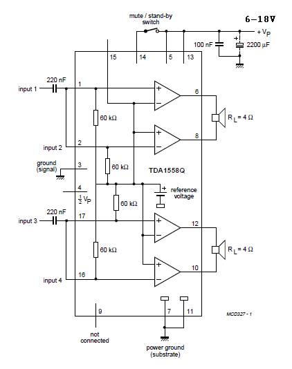
22Watt x 2 audio amplifier
A 22W x 2 audio amplifier circuit diagram utilizing the TDA 1558 integrated circuit from Philips. The TDA1558 is a monolithic integrated class-B output power amplifier housed in a 17-lead single-in-line (SIL) plastic package. This amplifier operates based on class...
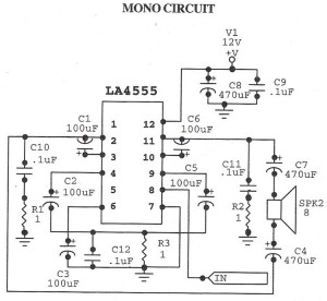
Audio Amplifier MonoCircuit With LA4555 IC
The following circuit illustrates an audio amplifier mono circuit diagram. This circuit is based on the LA4555 integrated circuit (IC). Features include a mono configuration and a power output of 2.3 watts.
The audio amplifier circuit utilizing the LA4555 IC is...
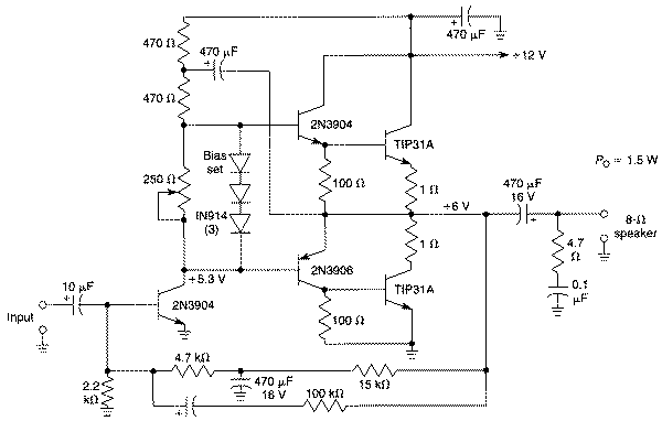
1.5W Audio power amplifier (12V)
Integrated circuits (ICs) have largely replaced traditional circuits like this one; however, this circuit is still utilized where the flexibility of a discrete device design is desirable. The components are readily available, and the issue of IC obsolescence is eliminated....

tda7262 stereo 20 watts audio amplifier circuit design
The TDA7262 integrated circuit, manufactured by ST Microelectronics, can be utilized to design a straightforward stereo audio amplifier project. This circuit can deliver a maximum output power of 20 watts per channel. The TDA7262 is a dual Hi-Fi audio power...