


Design A Low-Cost 4- To 20-mA Receiver Circuit For Control Loops
#4-20mA
#control loop
#analog-to-digital converter
#ADC
#current receiver
#industrial measurement
#signal conditioning
#low-cost design
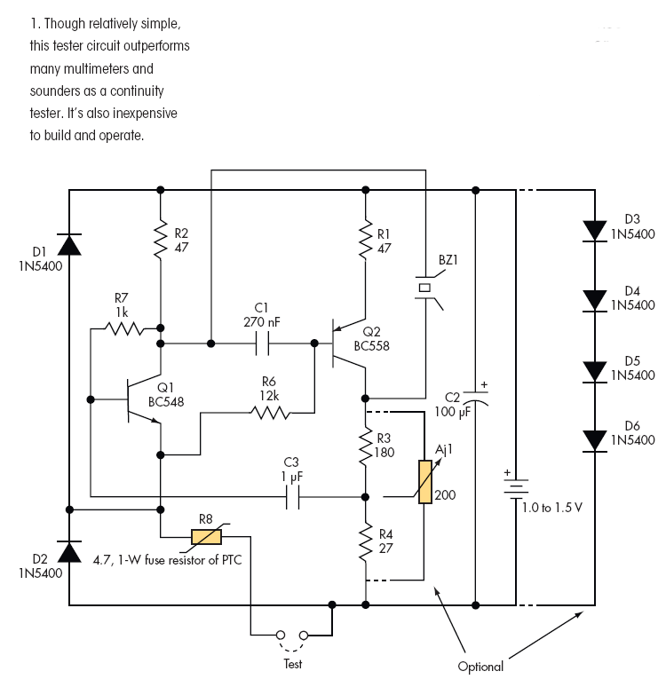
Description: Design a low-cost 4- to 20-mA receiver circuit for control loops using an analog-to-digital converter (ADC).
The design of a low-cost 4- to 20-mA receiver circuit is essential in industrial applications for monitoring and controlling processes. This current loop standard is widely used for transmitting analog signals over long distances, where the 4-20 mA range represents the minimum and maximum values of the measured variable. The receiver circuit is responsible for converting the current signal into a voltage signal suitable for further processing, typically by an analog-to-digital converter (ADC).
To construct the 4- to 20-mA receiver circuit, several key components are required. The circuit typically includes a precision resistor (shunt resistor) to convert the current signal into a voltage drop. The value of this resistor is chosen based on the desired output voltage range. For instance, using a 250-ohm resistor will yield a voltage output of 1V to 5V for a 4-20 mA input.
The output voltage from the shunt resistor is then fed into an operational amplifier configured as a non-inverting amplifier. This amplifier provides the necessary gain to ensure that the voltage level is appropriate for the ADC. The gain can be adjusted by selecting appropriate feedback and input resistors. Additionally, filtering capacitors may be included to reduce noise and improve the stability of the signal.
The ADC converts the amplified voltage signal into a digital format for processing by a microcontroller or other digital processing unit. The choice of ADC is critical, as it should have sufficient resolution and sampling rate to accurately represent the input signal. Commonly used ADCs in such applications include successive approximation ADCs or sigma-delta ADCs, which offer high resolution and good performance in noisy environments.
Power supply considerations are also important in the design. The circuit should be powered by a stable voltage supply, and appropriate decoupling capacitors should be used to minimize power supply noise. Additionally, protection circuits may be implemented to safeguard the receiver from overvoltage or reverse polarity conditions.
In summary, the design of a low-cost 4- to 20-mA receiver circuit involves careful selection of components, including a shunt resistor, operational amplifier, and ADC, along with considerations for power supply and signal integrity. This circuit plays a crucial role in enabling effective control loops in industrial automation systems.Design A Low-Cost 4- To 20-mA Receiver Circuit For Control Loops | analog-to-digital converter (ADC).
The design of a low-cost 4- to 20-mA receiver circuit is essential in industrial applications for monitoring and controlling processes. This current loop standard is widely used for transmitting analog signals over long distances, where the 4-20 mA range represents the minimum and maximum values of the measured variable. The receiver circuit is responsible for converting the current signal into a voltage signal suitable for further processing, typically by an analog-to-digital converter (ADC).
To construct the 4- to 20-mA receiver circuit, several key components are required. The circuit typically includes a precision resistor (shunt resistor) to convert the current signal into a voltage drop. The value of this resistor is chosen based on the desired output voltage range. For instance, using a 250-ohm resistor will yield a voltage output of 1V to 5V for a 4-20 mA input.
The output voltage from the shunt resistor is then fed into an operational amplifier configured as a non-inverting amplifier. This amplifier provides the necessary gain to ensure that the voltage level is appropriate for the ADC. The gain can be adjusted by selecting appropriate feedback and input resistors. Additionally, filtering capacitors may be included to reduce noise and improve the stability of the signal.
The ADC converts the amplified voltage signal into a digital format for processing by a microcontroller or other digital processing unit. The choice of ADC is critical, as it should have sufficient resolution and sampling rate to accurately represent the input signal. Commonly used ADCs in such applications include successive approximation ADCs or sigma-delta ADCs, which offer high resolution and good performance in noisy environments.
Power supply considerations are also important in the design. The circuit should be powered by a stable voltage supply, and appropriate decoupling capacitors should be used to minimize power supply noise. Additionally, protection circuits may be implemented to safeguard the receiver from overvoltage or reverse polarity conditions.
In summary, the design of a low-cost 4- to 20-mA receiver circuit involves careful selection of components, including a shunt resistor, operational amplifier, and ADC, along with considerations for power supply and signal integrity. This circuit plays a crucial role in enabling effective control loops in industrial automation systems.Design A Low-Cost 4- To 20-mA Receiver Circuit For Control Loops | analog-to-digital converter (ADC).
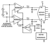
AD8225 High Resolution Analog/Digital Converter (ADC)Circuit and Datasheet
The Common Mode Rejection Ratio (CMRR) facilitates the rejection of high-frequency common-mode voltages, leading to the attenuation of elevated ambient noise levels from utility lines, industrial machinery, and other sources of radiation. The circuit diagram presented illustrates the advantages of...
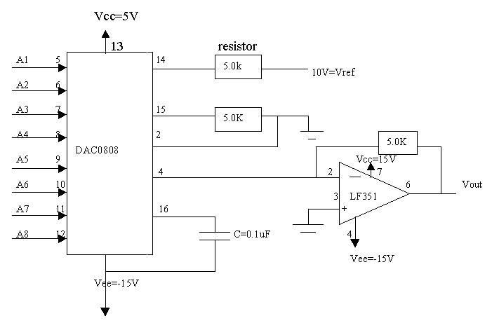
Signal Conditioners Information
Signal conditioning involves a series of operations applied to a signal to make it compatible for interfacing with other devices or systems. Signal conditioners are the devices that execute this operation, featuring both an input and an output. Typically, the...
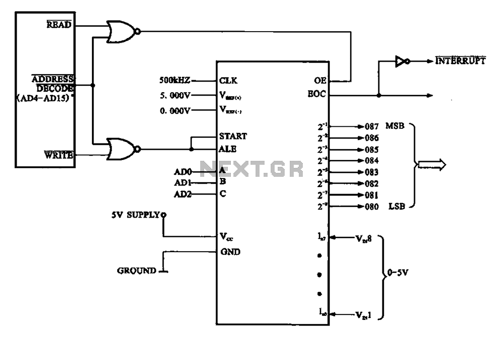
Using ADC 0808-ADC 0809 circuit chip consisting
An A/D conversion circuit is designed to convert analog voltage into a digital signal encoding circuit. It utilizes ADC0808/ADC0809 circuit chips, which can convert analog signals into an 8-bit digital output signal.
The A/D conversion circuit employs the ADC0808 or ADC0809...
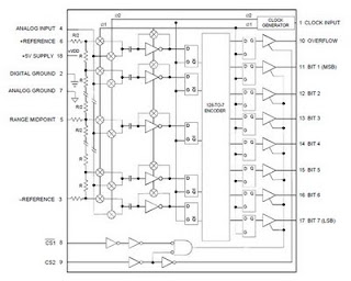
ADC 207 Flash Converting Schematic Diagram
The ADC 207 is the first analog-to-digital converter to utilize Flash Converting technology based on an advanced high-speed VLSI 1.2-micron CMOS process. This innovative process enhances the unique capabilities of the ADC 207, providing excellent speed, good linearity, and stable...
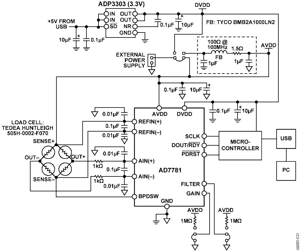
analog to digital converter ad7781
The AD7781 is a complete low-power front-end solution for bridge sensor products, including weigh scales, strain gauges, and pressure sensors. It contains a precision low-power 20-bit sigma-delta ADC, an on-chip low-noise programmable gain amplifier (PGA), and an on-chip oscillator. Consuming...
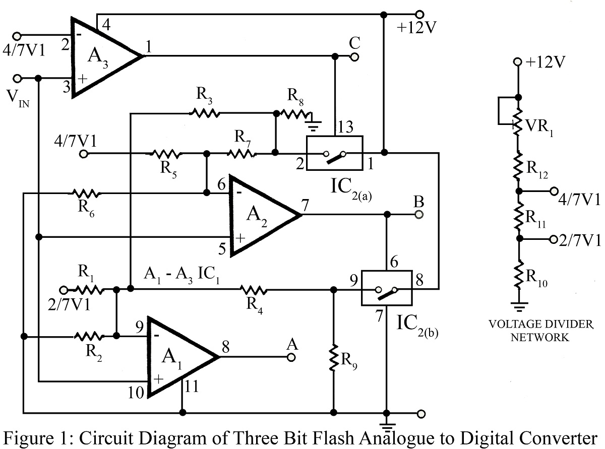
Three Bit flash Analog to Digital Converter Circuit
The flash type converter is the simplest and fastest type of analog-to-digital converter. The entire digital output word is available immediately after the propagation delay time of the comparators and the encoding logic gates. A typical conversion time for a...
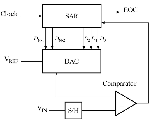
Successive Approximation ADC
An analog-to-digital converter is a device that converts a continuous quantity to a discrete time digital representation. An ADC may also provide an isolated measurement. An analog signal is any continuous signal where the time-varying feature represents another time-varying quantity....
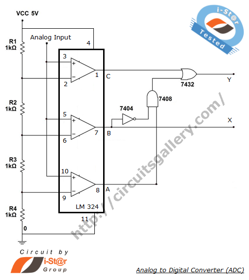
What is analog to digital converter ADC using LM324 IC
The process of converting an analog voltage into an equivalent digital signal is known as Analog to Digital Conversion (ADC). An ADC is an electronic circuit that converts its analog input to a corresponding binary value. The output depends on...
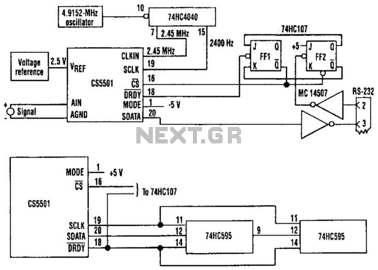
Adc Poller Circuit
The CS5501 16-bit delta-sigma analog-to-digital converter continuously converts signals, outputting conversion words to its output register every 1024 cycles of its master clock, as it lacks a start convert command. By integrating a standard dual J-K flip-flop into the circuit,...