


Digital Levels Scope Displays 2 Logic Signals On 1 Scope
#oscilloscope
#logic signals
#resistor circuit
#digital levels
#measurement
#electronics
#signal display
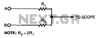
Description: This simple resistor circuit can be used to trick an oscilloscope into displaying two logic signals on one channel. By selecting R2 to be twice the value of R, the oscilloscope trace will show one of four distinct analog levels for each possible combination of the states of inputs A and B. The voltage levels observed by the oscilloscope are significantly influenced by the current-sourcing capability of the digital logic. Due to the necessity of using high resistances, this technique has a limited frequency range.
This circuit utilizes a resistor divider configuration to combine two digital logic signals, A and B, into a single output that can be visualized on an oscilloscope. The resistor values are critical in determining the resulting voltage levels displayed. By setting R2 to twice the resistance of R, the circuit can create four unique voltage levels corresponding to the logical states of A and B: both low (0V), A high and B low, A low and B high, and both high.
The voltage levels are derived from the following relationships:
- When both inputs are low (0V), the output voltage is at its lowest level.
- When A is high and B is low, the output voltage will be at a medium level determined by the resistor values.
- When A is low and B is high, the output voltage will be at another medium level.
- When both inputs are high, the output voltage reaches its maximum level.
It is essential to consider the current-sourcing capability of the digital logic driving the inputs, as this will affect how accurately the oscilloscope can display the intended voltage levels. High resistance values are required to minimize loading effects on the logic circuit, but this leads to a trade-off in frequency response. The circuit's ability to accurately represent fast-changing digital signals is limited, making it more suitable for lower frequency applications or for observing slower transitions in logic levels.
In summary, while this resistor circuit provides a useful method for visualizing multiple logic states on a single oscilloscope channel, careful consideration must be given to resistor values, the characteristics of the digital logic, and the limitations imposed by high resistance on the frequency response of the system. Using this simple resistor circuit, you can trick your oscilloscope into displayin g two logic signals on one channel. If you select R2 to be twice R, the scope trace will show one of four distinct analog levels for each possible combination of the states of inputs A and B. Of course, the voltage levels that your oscilloscope sees depends heavily on the current-sourc-ing capability of your digital logic.
Because you must use high resistances, this technique has a limited frequency range.
This circuit utilizes a resistor divider configuration to combine two digital logic signals, A and B, into a single output that can be visualized on an oscilloscope. The resistor values are critical in determining the resulting voltage levels displayed. By setting R2 to twice the resistance of R, the circuit can create four unique voltage levels corresponding to the logical states of A and B: both low (0V), A high and B low, A low and B high, and both high.
The voltage levels are derived from the following relationships:
- When both inputs are low (0V), the output voltage is at its lowest level.
- When A is high and B is low, the output voltage will be at a medium level determined by the resistor values.
- When A is low and B is high, the output voltage will be at another medium level.
- When both inputs are high, the output voltage reaches its maximum level.
It is essential to consider the current-sourcing capability of the digital logic driving the inputs, as this will affect how accurately the oscilloscope can display the intended voltage levels. High resistance values are required to minimize loading effects on the logic circuit, but this leads to a trade-off in frequency response. The circuit's ability to accurately represent fast-changing digital signals is limited, making it more suitable for lower frequency applications or for observing slower transitions in logic levels.
In summary, while this resistor circuit provides a useful method for visualizing multiple logic states on a single oscilloscope channel, careful consideration must be given to resistor values, the characteristics of the digital logic, and the limitations imposed by high resistance on the frequency response of the system. Using this simple resistor circuit, you can trick your oscilloscope into displayin g two logic signals on one channel. If you select R2 to be twice R, the scope trace will show one of four distinct analog levels for each possible combination of the states of inputs A and B. Of course, the voltage levels that your oscilloscope sees depends heavily on the current-sourc-ing capability of your digital logic.
Because you must use high resistances, this technique has a limited frequency range.
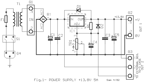
Electronics Projects Circuits
Over 1400 top electronics projects and electronic circuits with photos, datasheets, and easy-to-read schematics, along with explanations of how they work and how to build them.
The collection comprises a vast array of electronics projects suitable for enthusiasts and professionals alike....
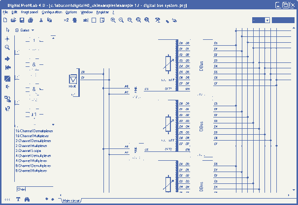
Digital-ProfiLab 4.0
Digital-ProfiLab was designed for measurement and control applications, combining features like circuit and logic simulation, front panel design, and hardware control to one powerful tool. Incoming signals from external devices may be processed and displayed. A circuit editor is used...
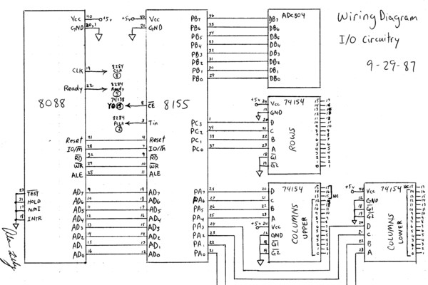
digital oscilloscope
This is an early test program (assembly source code) that was stored on the erasable programmable memory chip (EEPROM). Assembler programming is just one step above programming at the binary level.
The described early test program utilizes assembly language, which is...
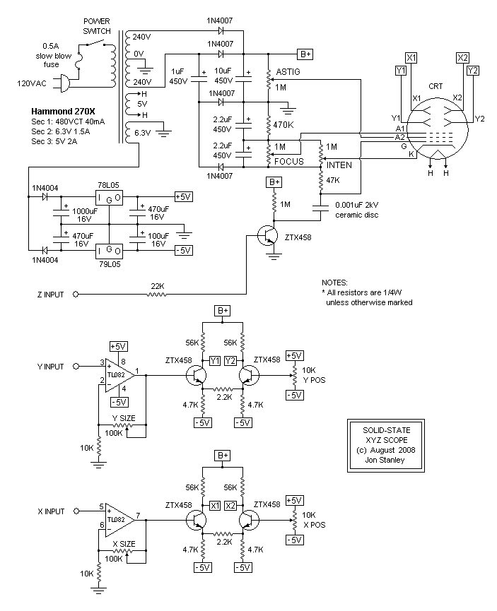
Ultra-Simple Oscilloscope
Simple homemade oscilloscopes are not difficult to design and build. Various designs dating back to the 1930s have been studied, leading to the development of a simple oscilloscope that electronics hobbyists can construct using readily available parts today. The first...
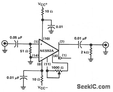
OSCILLOSCOPE COUNTER PREAMPLIFIER
The circuit provides a voltage gain of 20 ±0.1 dB within a frequency range of 500 kHz to 50 MHz. The low-frequency response of the amplifier can be enhanced by increasing the value of the 0.05 µF capacitor connected in...
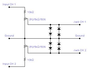
Interface Circuit for PC Soundcard Oscilloscope
For simple electronic circuits, it may be sufficient to gain qualitative insights on dedicated electrical signals. This interface circuitry allows the line-in input of a standard PC sound card to be utilized as a 2-channel oscilloscope. Although this setup does...
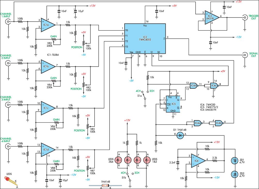
four channel oscilloscope
This circuit allows the simultaneous display of four signals using only one channel of an oscilloscope. It sequentially switches each input to the output while performing some signal conditioning. This configuration is designed for low-frequency signal measurements and lacks over-voltage...
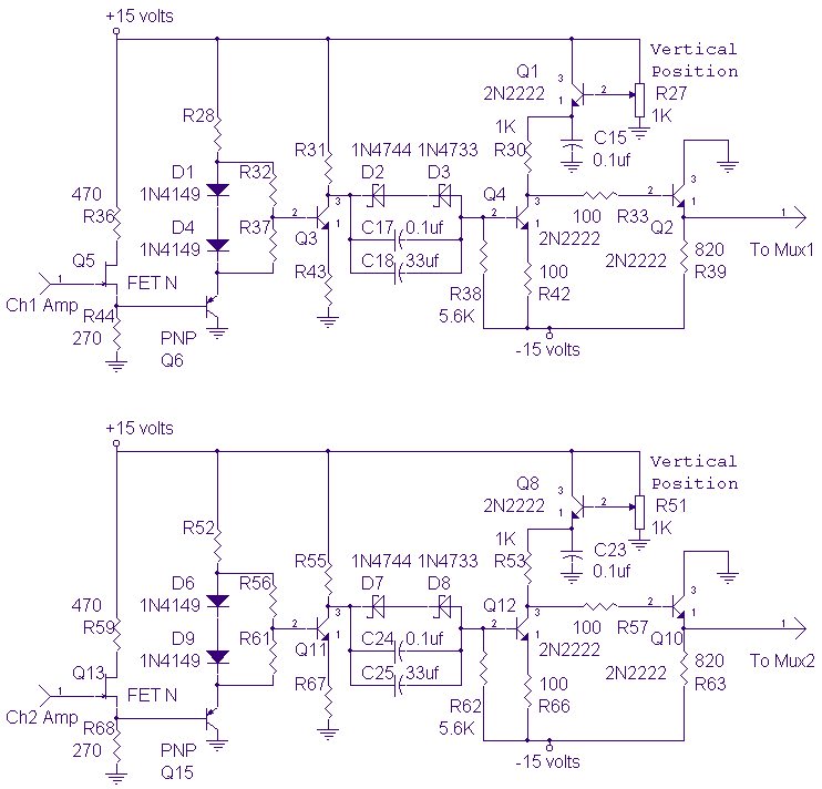
DC-10Mhz Amplifier for Oscilloscope
The DC-10 MHz amplifier shown below is identical for both scope channels. The input FET should be mounted directly on the adjustable attenuator switch for best frequency response. The vertical position pots, R27 and R51, change the dc level of...
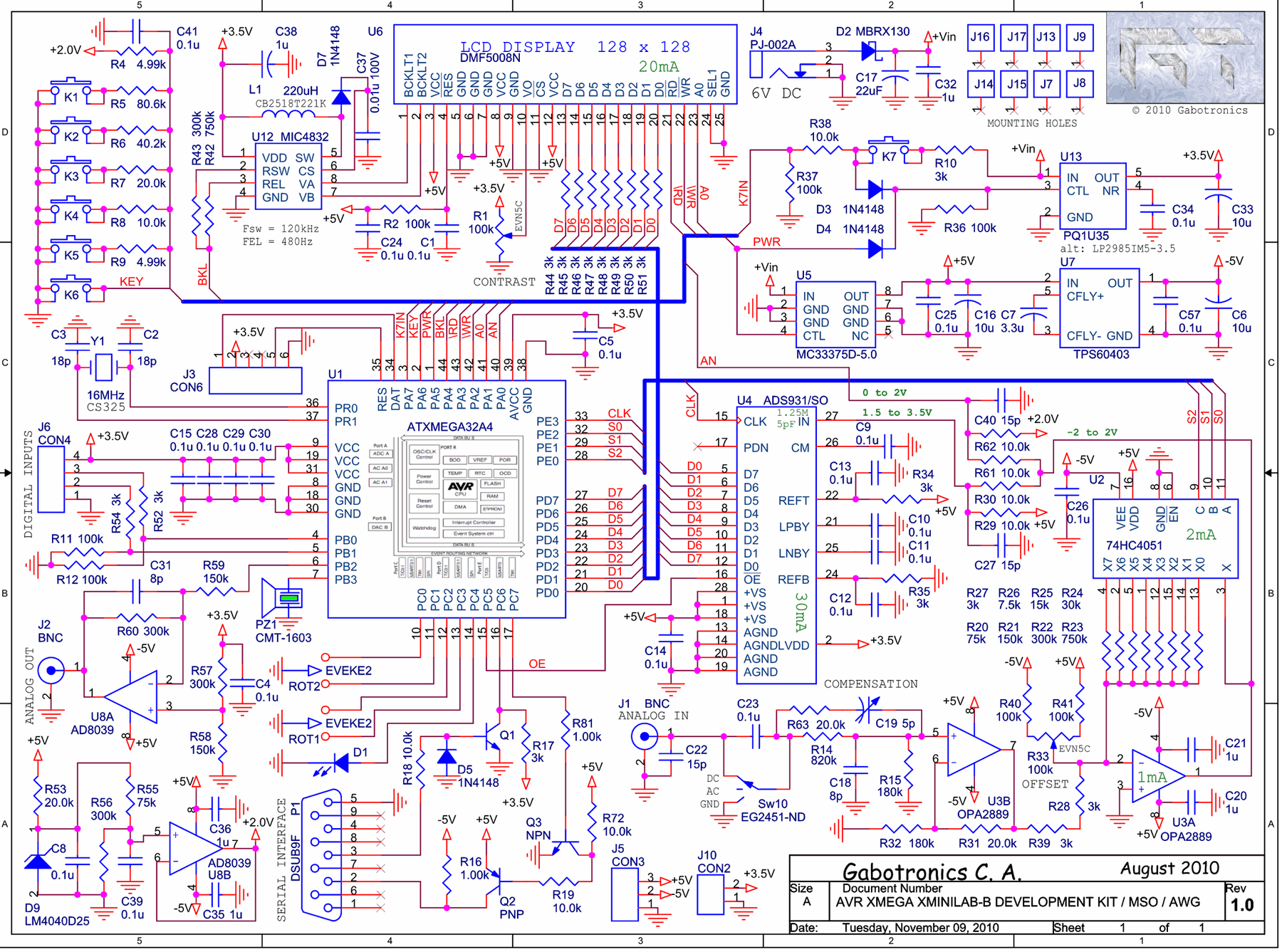
Oscilloscope Xminilab-B on the microcontroller Atmel AVR ATXMEGA32A4
The Xminilab-B oscilloscope is based on the Atmel AVR ATXMEGA32A4 microcontroller. It is designed as a debug board by the Gabotronis company, as noted on rlocman.ru.
The Xminilab-B oscilloscope features a compact and efficient design that leverages the capabilities of the...