


Digital temperature measuring
#temperature
#thermocouple
#voltage-to-frequency
#digital frequency meter
#analogue to digital
#measurement
#Celsius
#sensor
#converter
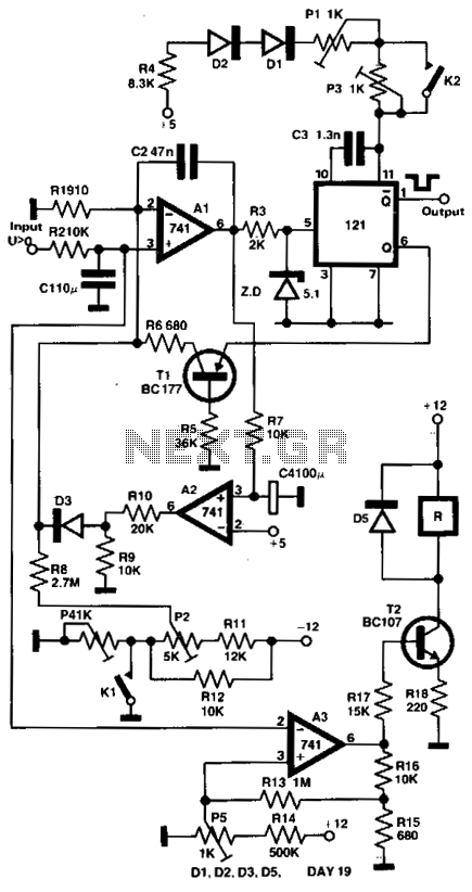
Description: The output voltage of a thermocouple is converted into a frequency that is measured by a digital frequency meter. The output signal from the thermocouple is proportional to the temperature difference between the hot junction and a reference thermostat maintained at 0°C. This signal drives a voltage-to-frequency converter, which transforms the analog input signal into an output frequency. The conversion ratio is adjusted so that the frequency corresponds directly to the measured temperature in degrees Celsius. For instance, at 350°C, the output frequency is 350 Hz. The measuring setup, utilizing a Ni-NiCr thermocouple, allows for temperature measurements within the range of 5°C to 800°C, with an accuracy of ±1°C.
The described system employs a thermocouple, specifically a Ni-NiCr type, which is known for its reliability and wide temperature range. The thermocouple generates a small voltage that varies with temperature, following the Seebeck effect. This voltage is then fed into a voltage-to-frequency converter (VFC), which is a critical component that translates the voltage signal into a frequency output.
The VFC operates by adjusting its conversion ratio, which is essential for ensuring that the frequency output is directly proportional to the temperature being measured. This linear relationship allows for straightforward interpretation of the frequency reading as a temperature value. For example, a frequency output of 350 Hz indicates a temperature of 350°C, making it easy to read and understand.
The digital frequency meter is connected to the output of the VFC, which captures the frequency signal and displays it in a user-friendly manner. This setup is particularly advantageous for applications requiring precise temperature monitoring and control, such as in industrial processes or laboratory environments.
The thermocouple's operational range of 5°C to 800°C, with a specified accuracy of ±1°C, makes this measuring system suitable for a variety of applications, including material testing, furnace temperature monitoring, and other high-temperature environments. The design of the system ensures that it can provide reliable and accurate temperature readings over its operational range, facilitating effective temperature management in various settings.The output voltage of a thermocouple is converted into frequency measured by a digital frequency meter. The output thermocouple signal is proportional to the temperature difference between the hot junction and the thermostat kept at 0°C, it drives the voltage-to-frequency converter changing the analogue input signal into the output frequency with the conversion ratio adjusted in such a way, that the frequency is equal to the measured temperature in Celsius degrees, e.g., for 350°C the frequency value is 350 Hz.
The measuring set connected with Ni-NiCr thermocouple permits you to measure the temperatures within the range of 5°C - 800°C with ±1°C error.
The described system employs a thermocouple, specifically a Ni-NiCr type, which is known for its reliability and wide temperature range. The thermocouple generates a small voltage that varies with temperature, following the Seebeck effect. This voltage is then fed into a voltage-to-frequency converter (VFC), which is a critical component that translates the voltage signal into a frequency output.
The VFC operates by adjusting its conversion ratio, which is essential for ensuring that the frequency output is directly proportional to the temperature being measured. This linear relationship allows for straightforward interpretation of the frequency reading as a temperature value. For example, a frequency output of 350 Hz indicates a temperature of 350°C, making it easy to read and understand.
The digital frequency meter is connected to the output of the VFC, which captures the frequency signal and displays it in a user-friendly manner. This setup is particularly advantageous for applications requiring precise temperature monitoring and control, such as in industrial processes or laboratory environments.
The thermocouple's operational range of 5°C to 800°C, with a specified accuracy of ±1°C, makes this measuring system suitable for a variety of applications, including material testing, furnace temperature monitoring, and other high-temperature environments. The design of the system ensures that it can provide reliable and accurate temperature readings over its operational range, facilitating effective temperature management in various settings.The output voltage of a thermocouple is converted into frequency measured by a digital frequency meter. The output thermocouple signal is proportional to the temperature difference between the hot junction and the thermostat kept at 0°C, it drives the voltage-to-frequency converter changing the analogue input signal into the output frequency with the conversion ratio adjusted in such a way, that the frequency is equal to the measured temperature in Celsius degrees, e.g., for 350°C the frequency value is 350 Hz.
The measuring set connected with Ni-NiCr thermocouple permits you to measure the temperatures within the range of 5°C - 800°C with ±1°C error.
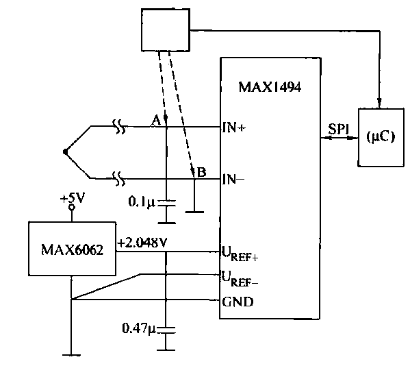
Thermocouple thermometer circuit
The circuit consists of the MAX1494 and a thermocouple temperature measurement system. The MAX1494 is terminated at 1N GND 5-32. An external temperature sensor, such as the DS75, can be utilized for junction temperature compensation. The MAX1494 employs an external...
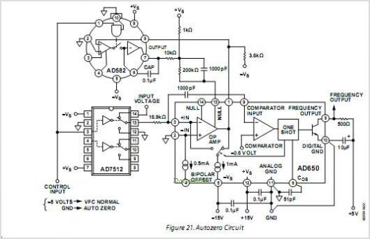
Voltage-to-Frequency And Frequency-to-Voltage Converter
The AD652 Synchronous Voltage-to-Frequency Converter (SVFC) is a robust component designed for precision analog-to-digital conversion, featuring a typical nonlinearity of 0.002% (maximum of 0.005%) at an output frequency of 100 kHz. Its inherent monotonicity in the transfer function and the...
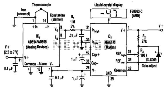
Single-Dc Supply Thermometer
Using a J-type thermocouple, this circuit can indicate temperatures from -350° to 400° with a 6-V supply or from -50° to +100° with a 3-V lithium battery. The AD954 produces a 10 mV/°C output to the MAX 138 digital voltmeter...
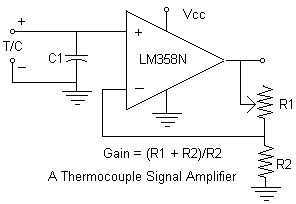
Simple Thermocouple Amplifier circuit
Continuing with the thermocouple interface concept, the next step is to amplify the TC's millivolt signal into a more readable analog voltage, on the order of 0 to 5VDC. This simple circuit fits the bill. The LM358N is a dual...
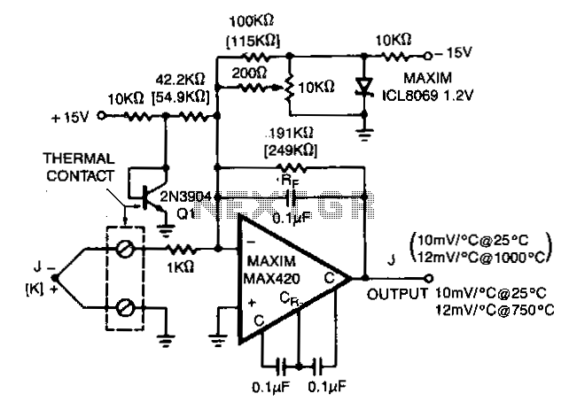
Thermocouple-preamplifier
The MAX420 is operated at a gain of 191 to convert the 52 µV/°C output of the type J thermocouple to a 10 mV/°C signal. The -2.2 mV/°C temperature coefficient of the 2N3904 is added into the summing junction with...
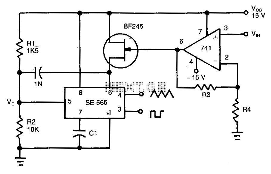
Wide-range-voltage-to-frequency-converter
This circuit operates based on the frequency variation of the function generator in relation to the input voltage (ViN). The frequency is influenced by the capacitance and resistor connected to pin 6, with the resistor being substituted by a Field...

Temperature Relay Circuit
This simple temperature relay circuit can be used to signal a fire or setpoint for temperature monitoring function. You need to adjust P1 so that T1's base.
The temperature relay circuit operates by monitoring the temperature in a designated area and...
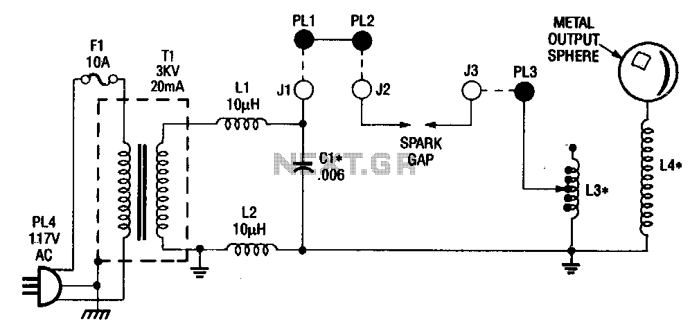
Differential-thermometer
The differential thermometer utilizes two probes to display the temperature difference between them instead of indicating the precise temperature. It employs a conventional meter as an indicator and has a total range of -10°C to 20°C.
The differential thermometer operates on...
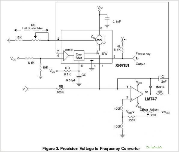
XR4151 XR4151 -Voltage-to-Frequency Converter
The purpose of this application note is to present an example circuit illustrating the operation of the XR-T5683 device at a data rate of 10.1 Mbps. This note includes the results of measurements taken on the XR-T5683 at this specific...