


DISPLAY BOARD FOR RADAR GUN
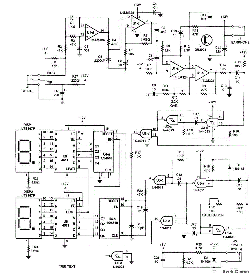
Description: This circuit receives a Doppler signal from a radar, amplifies and limits it, and then feeds the frequency into a counter (U4) and a display circuit (DISP1, DISP2, U5, U6). The calibration of the counter is determined by the clock circuit U2B, with calibration achieved through resistors R21 and R22. Resistor R21 can be adjusted if a kilometers per hour readout is preferred.
The described circuit is designed to process Doppler radar signals effectively. It begins by receiving the raw Doppler signal, which is typically a low-level analog signal. The first stage of the circuit involves amplification, where the weak radar signal is boosted to a more manageable level. This amplification is critical for ensuring that the subsequent processing stages can accurately interpret the signal.
Following the amplification, the signal undergoes a limiting stage. This is essential for eliminating noise and preventing signal distortion, which can occur due to fluctuations in the input signal. By limiting the signal, the circuit ensures that only the relevant frequency components are passed on to the next stage.
The processed frequency is then directed to a counter (U4), which counts the number of cycles of the incoming signal over a specified time period. This frequency information is crucial for calculating the speed of an object based on the Doppler effect. The counter's output is subsequently fed into a display circuit composed of components DISP1, DISP2, U5, and U6. This display circuit provides a visual representation of the speed measurement, allowing users to easily read the results.
Calibration of the counter is handled by the clock circuit (U2B), which generates a precise timing reference for the counting operation. Resistors R21 and R22 play a pivotal role in this calibration process. By adjusting R21, users can modify the scaling of the readout, enabling the display to show speed in kilometers per hour or other desired units. This flexibility in calibration ensures that the circuit can be tailored to meet specific application requirements.
Overall, this circuit exemplifies a robust design for radar signal processing, featuring amplification, limiting, counting, and display capabilities, all of which are essential for accurate speed measurements in various applications.This circuit takes signal (doppler) from a radar,un, amplifies and limits it, and feeds the frequency into a counter (U4) and display circuit (DISP1, DISP2,U5,U6). Counter calibration is set by clock circuit U2B. Calibration is obtained via R21 and R22. R21 can be changed if kilometers/hour readout is desired..
The described circuit is designed to process Doppler radar signals effectively. It begins by receiving the raw Doppler signal, which is typically a low-level analog signal. The first stage of the circuit involves amplification, where the weak radar signal is boosted to a more manageable level. This amplification is critical for ensuring that the subsequent processing stages can accurately interpret the signal.
Following the amplification, the signal undergoes a limiting stage. This is essential for eliminating noise and preventing signal distortion, which can occur due to fluctuations in the input signal. By limiting the signal, the circuit ensures that only the relevant frequency components are passed on to the next stage.
The processed frequency is then directed to a counter (U4), which counts the number of cycles of the incoming signal over a specified time period. This frequency information is crucial for calculating the speed of an object based on the Doppler effect. The counter's output is subsequently fed into a display circuit composed of components DISP1, DISP2, U5, and U6. This display circuit provides a visual representation of the speed measurement, allowing users to easily read the results.
Calibration of the counter is handled by the clock circuit (U2B), which generates a precise timing reference for the counting operation. Resistors R21 and R22 play a pivotal role in this calibration process. By adjusting R21, users can modify the scaling of the readout, enabling the display to show speed in kilometers per hour or other desired units. This flexibility in calibration ensures that the circuit can be tailored to meet specific application requirements.
Overall, this circuit exemplifies a robust design for radar signal processing, featuring amplification, limiting, counting, and display capabilities, all of which are essential for accurate speed measurements in various applications.This circuit takes signal (doppler) from a radar,un, amplifies and limits it, and feeds the frequency into a counter (U4) and display circuit (DISP1, DISP2,U5,U6). Counter calibration is set by clock circuit U2B. Calibration is obtained via R21 and R22. R21 can be changed if kilometers/hour readout is desired..
Amplifier Timer Circuit Schematic
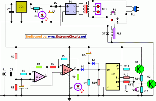
This circuit turns off an amplifier or any other device when a low-level audio signal fed to its input is absent for at least 15 minutes. Pressing P1 switches the device on, supplying power to any appliance connected to SK1....
Bootstrapped Amp Current Source
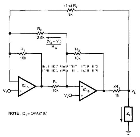
This circuit responds to the difference between Vj and V2. Rq sets the gain. Resistors XR2 and (1 - X) R2 produce the bootstrap effect. These two resistors convert the circuit's output voltage to a current. IC1 and IC2 are...
Ignition pulses counter
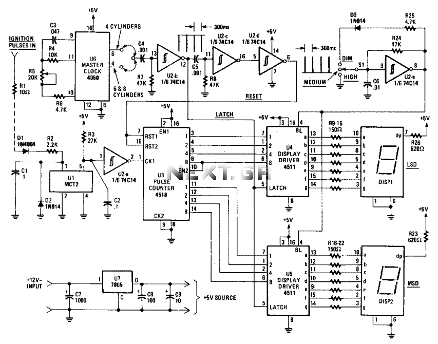
The Digi-Tach includes a master clock circuit (U6), latch and reset pulse generators (U2-b to U2-d), an input signal conditioner (U1, U2-a), a pulse counter (U3), display components and drivers (DIS1, DIS2, U4, and U5), as well as a voltage...
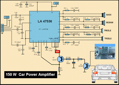
Schematic MP3 Car Audio Power AmplifierCircuits
This is a diagram of a car audio active loudspeaker utilizing the LF353 operational amplifier from National Semiconductor. For optimal performance, the NE5532 is recommended to split the audio signal into three frequency bands using an active filter. The SANYO...
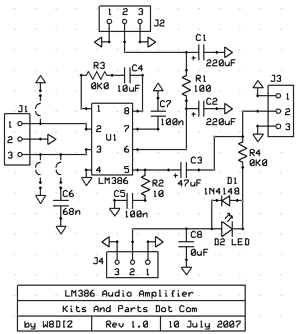
audio amp
Install the red LED at D2. Align the flat side of the LED with the PCB outline. Install a jumper wire at R4 and install a 220µF electrolytic capacitor at C8 with the negative side connected to ground. Connect pin...
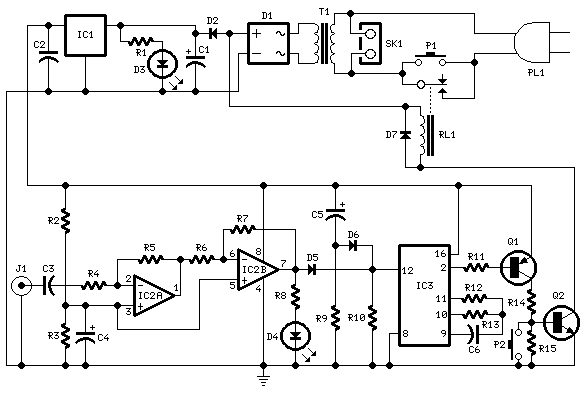
Amplifier Timer
Turns off your amplifier when idle for 15 minutes. Fed by amplifier tape-output. This circuit turns off an amplifier or any other device when a low-level audio signal fed to its input is absent for 15 minutes at least. Pushing...
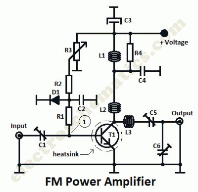
Radio Amplifiers Circuits
This is a 1 watt FM amplifier with a robust design that can be used to amplify an RF signal in the 88 to 108 MHz band. It is highly sensitive when utilizing quality RF power amplifier transistors, trimmers, and...
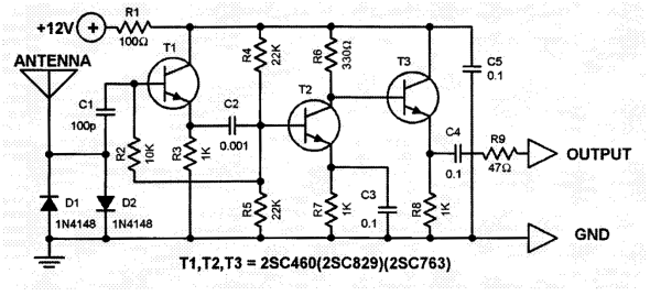
Car Antenna Amplifier Circuit
The total gain of the car antenna amplifier is approximately 30 dB, with an input impedance of around 10 kΩ at 30 MHz. The amplifier should be mounted directly at the base of the antenna to prevent signal losses attributed...
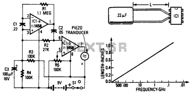
Radar Detector
A simple radar signal detector utilizes the junctions of the input transistors of an LM1458 operational amplifier as RF detectors. The leads of the integrated circuit function as an antenna and should be approximately 0.4 inches long, measured from the...