


Distortion Analyzer
#distortion analyzer
#THD measurement
#pre-distortion circuit
#sine wave generator
#linearizer circuit
#audio measurement
#test equipment
#electronics lab
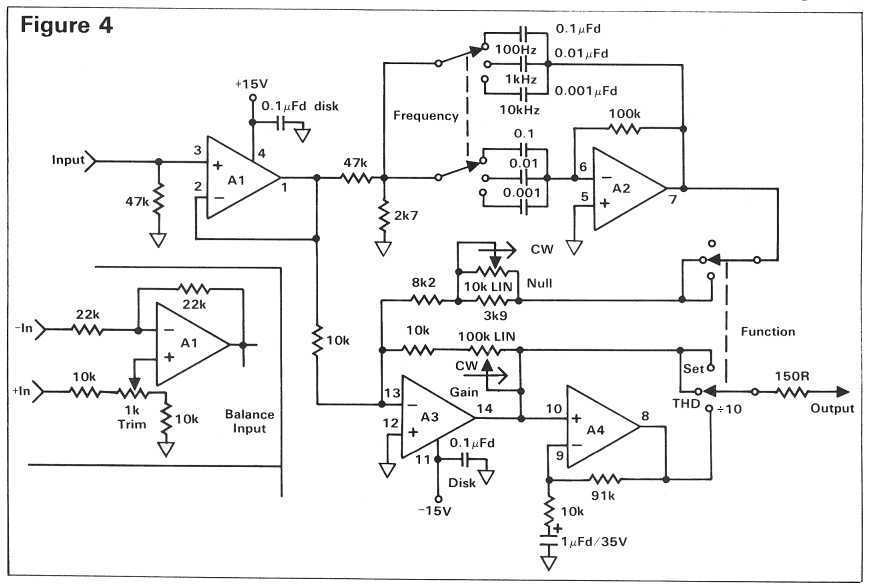
Description: The pre-distortion circuit described here is extremely simple and only requires one trimmer adjustment, though you will need an accurate way to measure THD in order to achieve the best results. A dedicated distortion analyzer to help you adjust the linearizer circuit is shown later in this article. This analyzer has turned out to be one of the most useful little gadgets I have, given its simplicity and incredibly low price. The only thing keeping it from being lab quality is that it uses switched rather than continuously tuned frequencies. Therefore, you must adjust your sine wave generator to match its frequencies, rather than the other way around. At the heart of any THD meter is a notch filter that can completely remove the original test frequency. After filtering, it is an easy task to measure the harmonics and noise that remain, and relate them to the total signal as a percentage. It also helps.
The pre-distortion circuit is designed to improve linearity in amplifiers by compensating for distortion before it occurs. This circuit typically utilizes a feedback mechanism that adjusts the input signal based on the output signal's characteristics. The single trimmer adjustment mentioned allows for fine-tuning of the circuit to optimize performance for specific applications or component tolerances.
In the context of total harmonic distortion (THD) measurement, the circuit operates in conjunction with a dedicated distortion analyzer. This analyzer employs a notch filter, which is a critical component that effectively eliminates the fundamental frequency from the signal being analyzed. By removing this frequency, the analyzer can focus on the harmonics and noise present in the output, enabling accurate calculations of distortion percentages.
The use of switched frequencies in the analyzer, while a limitation compared to continuously tuned systems, is offset by the affordability and simplicity of the device. Users are required to adjust their sine wave generator to align with the analyzer's frequency settings, which is a straightforward process but necessitates precision to ensure accurate readings.
Overall, this pre-distortion circuit and its associated measurement tools form a practical solution for audio engineers and technicians aiming to enhance the fidelity of their audio systems by minimizing distortion. Proper setup and calibration are essential for achieving optimal results, making the understanding of both the circuit and measurement techniques critical for effective application.The pre-distortion circuit described here is extremely simple (Figure 1) and only requires one trimmer adjustment, though you`ll need an accurate way to measure THD in order to achieve the best results. A dedicated distortion analyzer to help you adjust the linearizer circuit is shown later in this article.
This analyzer has turned out to be one of the most useful little gadgets I have, given its simplicity and incredibly low price. The only thing keeping it from being lab quality is that it uses switched rather than continuously tuned frequencies.
Therefore, you must adjust your sine wave generator to match its frequencies, rather than the other way around. At the heart of any THD meter is a notch filter that can completely remove the original test frequency. After filtering, it is an easy task to measure the harmonics and noise that remain, and relate them to the total signal as a percentage.
It also helps
The pre-distortion circuit is designed to improve linearity in amplifiers by compensating for distortion before it occurs. This circuit typically utilizes a feedback mechanism that adjusts the input signal based on the output signal's characteristics. The single trimmer adjustment mentioned allows for fine-tuning of the circuit to optimize performance for specific applications or component tolerances.
In the context of total harmonic distortion (THD) measurement, the circuit operates in conjunction with a dedicated distortion analyzer. This analyzer employs a notch filter, which is a critical component that effectively eliminates the fundamental frequency from the signal being analyzed. By removing this frequency, the analyzer can focus on the harmonics and noise present in the output, enabling accurate calculations of distortion percentages.
The use of switched frequencies in the analyzer, while a limitation compared to continuously tuned systems, is offset by the affordability and simplicity of the device. Users are required to adjust their sine wave generator to align with the analyzer's frequency settings, which is a straightforward process but necessitates precision to ensure accurate readings.
Overall, this pre-distortion circuit and its associated measurement tools form a practical solution for audio engineers and technicians aiming to enhance the fidelity of their audio systems by minimizing distortion. Proper setup and calibration are essential for achieving optimal results, making the understanding of both the circuit and measurement techniques critical for effective application.The pre-distortion circuit described here is extremely simple (Figure 1) and only requires one trimmer adjustment, though you`ll need an accurate way to measure THD in order to achieve the best results. A dedicated distortion analyzer to help you adjust the linearizer circuit is shown later in this article.
This analyzer has turned out to be one of the most useful little gadgets I have, given its simplicity and incredibly low price. The only thing keeping it from being lab quality is that it uses switched rather than continuously tuned frequencies.
Therefore, you must adjust your sine wave generator to match its frequencies, rather than the other way around. At the heart of any THD meter is a notch filter that can completely remove the original test frequency. After filtering, it is an easy task to measure the harmonics and noise that remain, and relate them to the total signal as a percentage.
It also helps
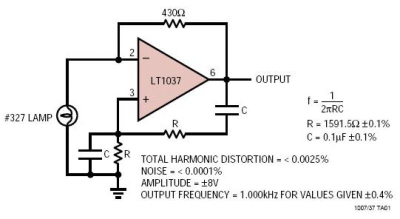
LT1007/LT1037 Ultrapure 1kHz Sine Wave Generator
A lamp provides amplitude stability while the very low noise amplifier generates a pure sine wave signal. The resistance and capacitance values determine the oscillator frequency, while the feedback resistor regulates the lamp current and output amplitude.
The circuit described consists...
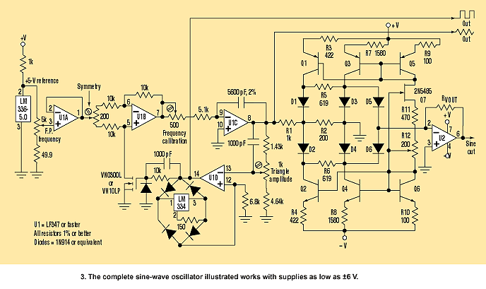
Battery-Powered Sine Generator Covers 100 Hz To 10 kHz
This circuit is a modified version of a function-generator circuit. It features a battery-powered sine wave generator that can be continuously adjusted from 100 Hz to 10 kHz.
The described circuit utilizes a sine wave generator to produce a continuous oscillating...
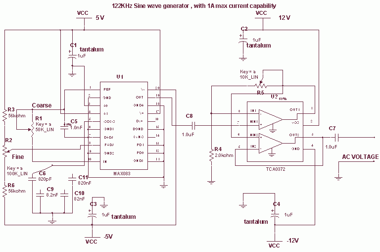
Frequency Sine wave generator with MAX083
This circuit uses the versatile MAX038 function generator. Although in this circuit some of the advanced characteristics of this IC are disabled, you can generate Sine, Triangle, Square waves (adjusting A0 and A1 pins see datasheet on www.maxim-ic.com if you...
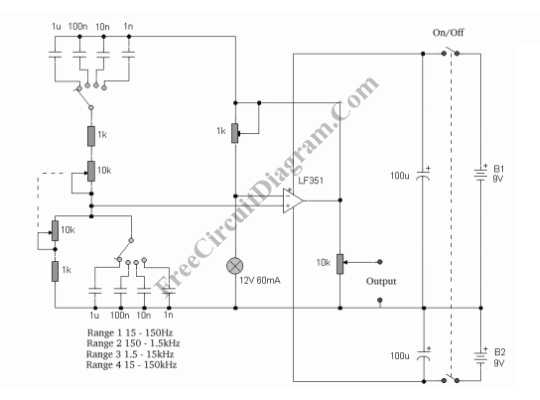
Variable Frequency Sinewave Generator
This sine wave generator is adjustable between 15 Hz and 150 kHz. The circuit is essentially a Wien-bridge oscillator, featuring multiple capacitor selections.
The sine wave generator operates on the principle of the Wien-bridge oscillator, which is known for producing low-distortion...

reference design digitally controlled sine wave generator
The circuit illustrated in Figure 1 generates a precise variable-frequency sine wave intended for use as a general-purpose reference signal. It incorporates an 8th-order elliptic switched-capacitor low-pass filter (IC3), which is clocked by a 100 kHz square wave produced by...
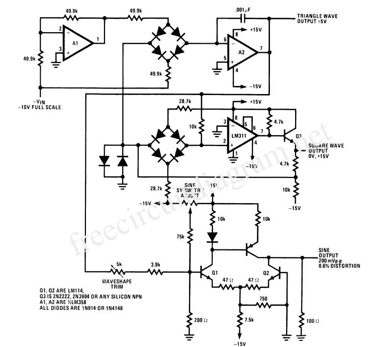
Sine Wave VFC to Use with PLL
The voltage-to-frequency converter (VFC) in this circuit produces a satisfactory sine-shaped output; however, it lacks good voltage-to-frequency linearity and exhibits a frequency stability of approximately 0.2%. The LM331 is an excellent choice for a linear and stable voltage-to-frequency converter, providing...