


dmm fuse protector
#DMM
#fuse protector
#current limiter
#input protection
#500 mA
#resistor
#voltage drop
#measurement safety
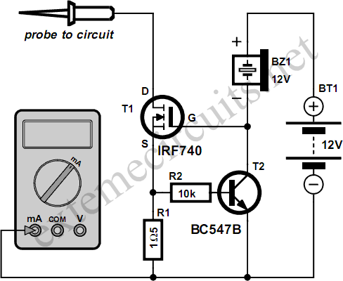
Description: Typically, the input protection fuse of a digital multimeter (DMM) will blow during a demonstration or an exciting phase of construction work. Spare fuses are often difficult to find, and if available, they take a considerable amount of time to install. This circuit replaces the fuse with a 500 mA current limiter. When resistor R1 passes approximately 500 mA, it will drop 0.75 V, which is sufficient to activate transistor T2. The buzzer functions as a pull-up resistor and serves as a loud acoustic warning device, causing the voltage at the gate of power FET T1 to drop to a level that limits the drain-source current to a safe value of around 500 mA. The excess energy resulting from the current limiting action is dissipated by the FET. Cooling is necessary in situations where the dissipation could exceed 1-2 watts. Without cooling, the voltage across the FET will be limited to 4V (2 W = 0.5 A × 4 V). Although an IRF740S is specified in the circuit diagram, nearly any power FET can be utilized. The BUZ10, for example, is a suitable option for high power dissipation. If a 12-V mini battery is employed, the buzzer should also be a 12-V device. However, the circuit will function properly with the more commonly available (and typically less expensive) 9-V battery and a compatible buzzer. If the buzzer is not required, it can be replaced with a 10-kΩ resistor.
This circuit design serves as an effective solution for protecting the input of a digital multimeter by employing a current limiting mechanism rather than a traditional fuse. The core components include a resistor (R1), a power FET (T1), a secondary transistor (T2), and a buzzer for acoustic signaling.
The operation begins when the current through R1 approaches the 500 mA threshold. At this point, the voltage drop across R1 reaches 0.75 V, triggering T2. This action causes T1 to enter a state where it limits the current flowing through the load to approximately 500 mA, thus protecting the DMM from potential damage due to excessive current.
The selection of the power FET is crucial, as it must be capable of handling the expected power dissipation. The IRF740S is a robust option, but alternatives like the BUZ10 can also be employed for applications requiring higher power handling capabilities. The design includes a consideration for thermal management; if the power dissipation in the FET is expected to exceed 1-2 watts, appropriate heat sinks or cooling mechanisms must be implemented to prevent thermal failure.
For power supply, the circuit can operate with either a 12-V or a 9-V battery. The choice of battery affects the type of buzzer used; a 12-V buzzer is required for a 12-V battery, while a 9-V battery can utilize a matching buzzer or, if the buzzer is unnecessary, a 10-kΩ resistor can be used instead to maintain circuit integrity.
Overall, this current limiting circuit provides a reliable alternative to fuses, ensuring that the digital multimeter remains protected during use while also offering an audible warning to alert users of the current limiting action.Typically the input protection fuse of your DMM will blow in the middle of a demonstration or an exciting phase of your construction work. Spare fuses are always hard to find, and if available take a lot of time to install. This circuit replaces the fuse by a 500 mA current limiter. When resistor R1 passes about 500 mA, it will drop 0. 75 V which is sufficient to switch on T2. With the buzzer acting as a pull-up resistor (and, of course, as a very loud acoustic warning device), the voltage at the gate of power FET T1 will drop to a level at which the drain-source current is limited to a safe value of about 500 mA. Of course, the excess energy caused by the current limiting action is dissipated by the FET. Cooling is required in all cases where the dissipation can be expected to exceed about 1-2 watts. After all, without cooling, the voltage allowed to occur across the FET will be just 4V (2 W = 0. 5 A G— 4 V). Although an IRF740S is indicated in the circuit diagram, almost any power FET may be used. The popular BUZ10, for example, is a good choice when a lot of power has to be dissipated. If a 12-V mini battery is used then the buzzer should also be a 12-V device. However the circuit will also work ¬ne from the more commonly found (and certainly less expensive) 9-V battery and a matching buzzer.
If the latter is not required it is simply replaced by a 10-k resistor.
This circuit design serves as an effective solution for protecting the input of a digital multimeter by employing a current limiting mechanism rather than a traditional fuse. The core components include a resistor (R1), a power FET (T1), a secondary transistor (T2), and a buzzer for acoustic signaling.
The operation begins when the current through R1 approaches the 500 mA threshold. At this point, the voltage drop across R1 reaches 0.75 V, triggering T2. This action causes T1 to enter a state where it limits the current flowing through the load to approximately 500 mA, thus protecting the DMM from potential damage due to excessive current.
The selection of the power FET is crucial, as it must be capable of handling the expected power dissipation. The IRF740S is a robust option, but alternatives like the BUZ10 can also be employed for applications requiring higher power handling capabilities. The design includes a consideration for thermal management; if the power dissipation in the FET is expected to exceed 1-2 watts, appropriate heat sinks or cooling mechanisms must be implemented to prevent thermal failure.
For power supply, the circuit can operate with either a 12-V or a 9-V battery. The choice of battery affects the type of buzzer used; a 12-V buzzer is required for a 12-V battery, while a 9-V battery can utilize a matching buzzer or, if the buzzer is unnecessary, a 10-kΩ resistor can be used instead to maintain circuit integrity.
Overall, this current limiting circuit provides a reliable alternative to fuses, ensuring that the digital multimeter remains protected during use while also offering an audible warning to alert users of the current limiting action.Typically the input protection fuse of your DMM will blow in the middle of a demonstration or an exciting phase of your construction work. Spare fuses are always hard to find, and if available take a lot of time to install. This circuit replaces the fuse by a 500 mA current limiter. When resistor R1 passes about 500 mA, it will drop 0. 75 V which is sufficient to switch on T2. With the buzzer acting as a pull-up resistor (and, of course, as a very loud acoustic warning device), the voltage at the gate of power FET T1 will drop to a level at which the drain-source current is limited to a safe value of about 500 mA. Of course, the excess energy caused by the current limiting action is dissipated by the FET. Cooling is required in all cases where the dissipation can be expected to exceed about 1-2 watts. After all, without cooling, the voltage allowed to occur across the FET will be just 4V (2 W = 0. 5 A G— 4 V). Although an IRF740S is indicated in the circuit diagram, almost any power FET may be used. The popular BUZ10, for example, is a good choice when a lot of power has to be dissipated. If a 12-V mini battery is used then the buzzer should also be a 12-V device. However the circuit will also work ¬ne from the more commonly found (and certainly less expensive) 9-V battery and a matching buzzer.
If the latter is not required it is simply replaced by a 10-k resistor.
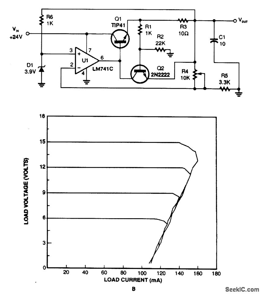
FOLDBACK CURRENT LIMITER
This regulator utilizes the voltage drop across resistor R3 to monitor current draw. When the current exceeds a certain threshold, Q2 is activated, which in turn disables Q1 and reduces the output voltage. Current limiting takes place when Q2 experiences...
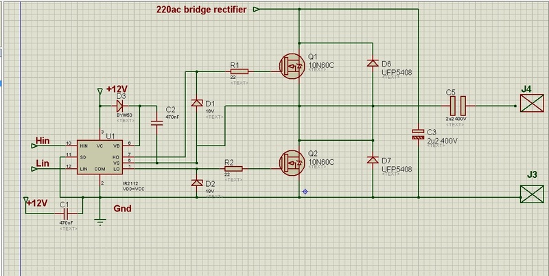
transducer current limiter circuit
This circuit is designed to drive an ultrasonic transducer. A question has arisen regarding how to limit the output current, as a 60W transducer may be at risk of damage due to excessive current. Guidance or examples for integrating a...
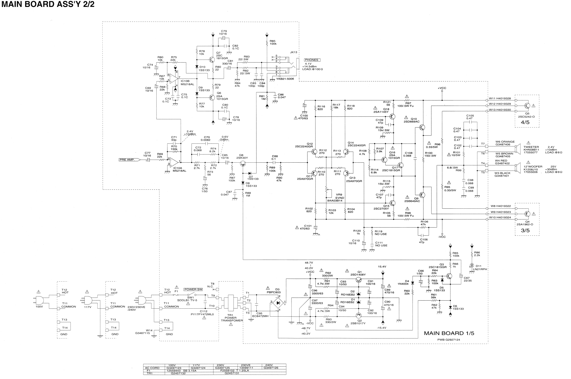
I burned out some resistors on the circuit board of my Roland
Some resistors on the circuit board of a Roland KC-300 amplifier have burned out and are so charred that their specifications cannot be determined. The resistors in question are R82, R83, R85, R92, and R93. Resistors R92 and R93 are...
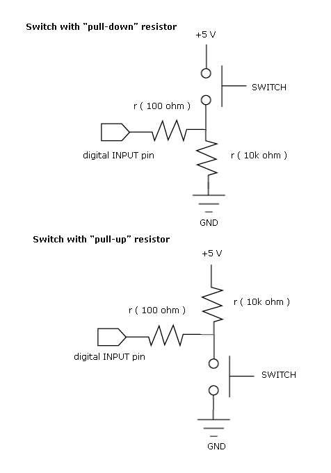
pull up and pull down resistor
Most beginners in digital electronics assume that a floating input represents a logic 0, which is a misconception. Floating inputs are in a neutral state and can represent either a logic 0 or a logic 1. This misunderstanding can lead...
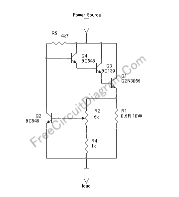
Variable (Adjustable) Current Limiter Circuit
This circuit provides automatic current limiting up to 8.4 A. Unlike current limiters that use only a resistor, this current limiting circuit does not drop the voltage significantly or keeps the voltage drop to a minimum until a specific current...
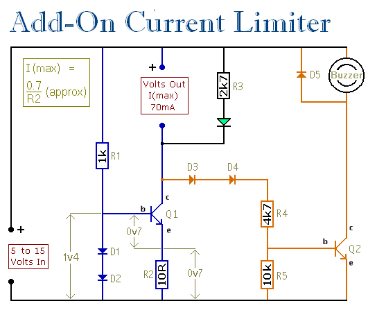
Current Limiter - Support Material
This circuit establishes a maximum limit on the current available from the output terminals by controlling the maximum current that can flow through Q1. The output terminals are in series with Q1, meaning that limiting the current through Q1 also...
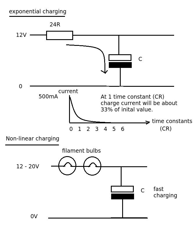
Transistor current limit circuit power handling
Designing a simple current limiter that charges a large 4.7mF capacitor with a charge current of approximately 500mA from a supply voltage of 10-20V. The dilemma is that there are existing MMBT2222A transistors available, which would be preferable to utilize...
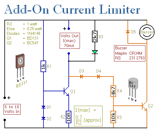
An Add-on Current Limiter
This circuit allows for the establishment of a maximum output current limit from a power supply unit (PSU). It is particularly beneficial when initially powering a project or conducting a soak test. By imposing an upper current limit, protection is...
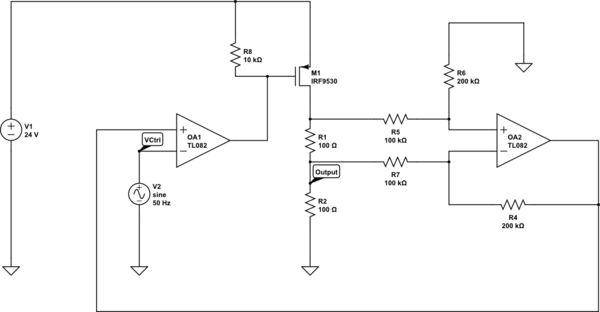
op amp Why does this current limiter circuit oscillate
Create a 0-25 mA current limiter using a control voltage input of 0-5 V to regulate the current through a resistive load (R2), which can vary between 0-200 ohms. The O2 operational amplifier (op-amp) functions as a differential amplifier with...