


Duty-Cycle Measurer
#duty cycle
#A/D converter
#pulse train
#Intersil 7101
#measurement
#percentage display
#digital display
#signal analysis
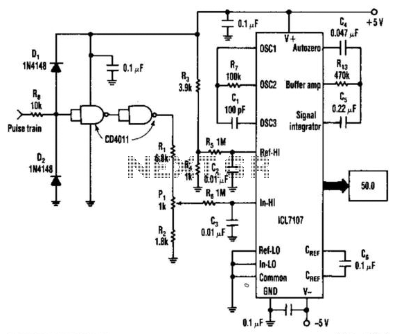
Description: An Intersil 7101 31/2-digit A/D converter is utilized to display the duty cycle of a pulse train as a percentage. The frequency range of this circuit is from 100 Hz to 250 kHz. CMOS gates are employed to convert the pulse train to a constant amplitude. This amplitude is subsequently compared to a reference voltage of 1 V, which is derived from resistors R3 and R4. PI is included for calibration purposes.
The circuit operates by first capturing the incoming pulse train, which can vary in frequency between 100 Hz and 250 kHz. The Intersil 7101 A/D converter is designed to process this signal and convert it into a digital representation that reflects the duty cycle as a percentage. The duty cycle is defined as the ratio of the time the signal is high to the total period of the signal.
To ensure accurate conversion, the CMOS gates function to stabilize the pulse train by converting it into a constant amplitude signal. This step is crucial as it allows for a consistent input to the A/D converter. The constant amplitude signal is then compared against a reference voltage of 1 V, which is established through a voltage divider configuration using resistors R3 and R4. This reference voltage serves as a baseline for the A/D conversion process.
Calibration is an essential aspect of this circuit, and it is facilitated by the inclusion of a proportional integral (PI) controller. The PI controller adjusts the output based on the difference between the measured duty cycle and the desired duty cycle, thereby enhancing the accuracy of the displayed results.
Overall, this circuit design effectively measures and displays the duty cycle of a pulse train over a wide frequency range, providing a reliable tool for applications requiring precise duty cycle measurements. An Intersil 7101 31/2-digit A/D converter is used to display the duty cycle of a pulse train as a percentage. The frequ ency range of this circuit is 100 Hz to 250 kHz. The CMOS gates convert the pulse train to constant amplitude. This amplitude is then compared to a reference of 1 V, derived from R3 and R4. PI is for calibration.
The circuit operates by first capturing the incoming pulse train, which can vary in frequency between 100 Hz and 250 kHz. The Intersil 7101 A/D converter is designed to process this signal and convert it into a digital representation that reflects the duty cycle as a percentage. The duty cycle is defined as the ratio of the time the signal is high to the total period of the signal.
To ensure accurate conversion, the CMOS gates function to stabilize the pulse train by converting it into a constant amplitude signal. This step is crucial as it allows for a consistent input to the A/D converter. The constant amplitude signal is then compared against a reference voltage of 1 V, which is established through a voltage divider configuration using resistors R3 and R4. This reference voltage serves as a baseline for the A/D conversion process.
Calibration is an essential aspect of this circuit, and it is facilitated by the inclusion of a proportional integral (PI) controller. The PI controller adjusts the output based on the difference between the measured duty cycle and the desired duty cycle, thereby enhancing the accuracy of the displayed results.
Overall, this circuit design effectively measures and displays the duty cycle of a pulse train over a wide frequency range, providing a reliable tool for applications requiring precise duty cycle measurements. An Intersil 7101 31/2-digit A/D converter is used to display the duty cycle of a pulse train as a percentage. The frequ ency range of this circuit is 100 Hz to 250 kHz. The CMOS gates convert the pulse train to constant amplitude. This amplitude is then compared to a reference of 1 V, derived from R3 and R4. PI is for calibration.
Pulse Train
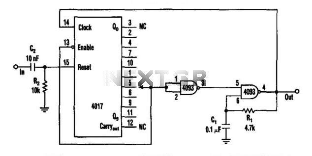
This circuit features a rate multiplier utilizing a 4093 Schmitt trigger configured as an oscillator, which drives a 4017 decade counter. When a pulse is present at the input (to C2), the 4017 is reset, causing output zero to go...
RealView 2.0
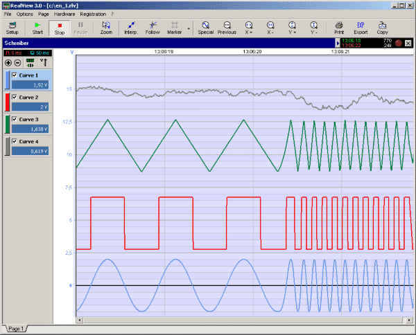
RealView is a measurement application, which records and plots measured values from analogue hardware devices in real-time. Several curves can be plotted into a single diagram. Several diagrams can be arranged on one or more pages if necessary. Plot options...
gear display
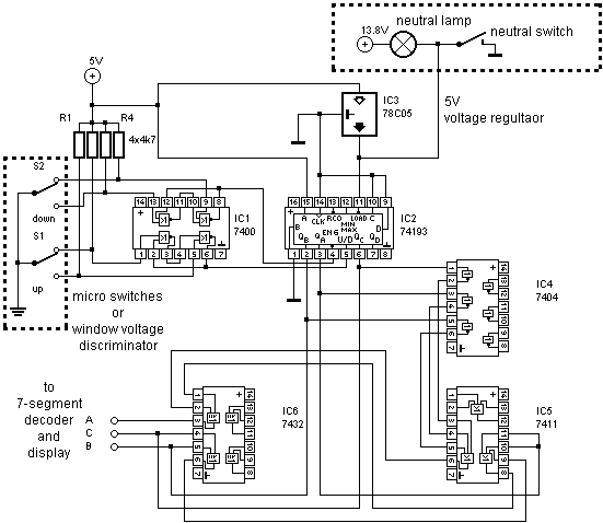
A universal digital gear display that can be installed on any motorbike. This is a low-cost solution based on simple TTL digital technology without software programming.
The universal digital gear display is designed for easy installation on a variety of motorbike...
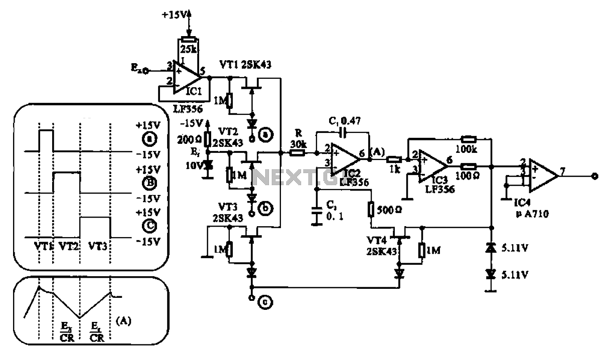
LF356 composed of AD converter
An A/D converter transforms an analog signal into a digital format. Various circuit configurations exist, as illustrated in Figures 21-24, which depict the structure of an A/D converter. One practical circuit configuration utilizes the integrated circuit LF356.
The A/D converter is...
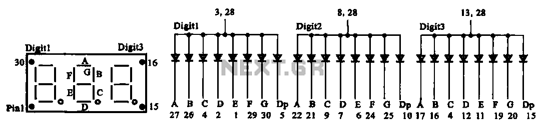
Digital display circuit configuration
The document presents two types of digital display circuits. The first type (a) utilizes a common anode circuit configuration, while the second type (b) employs a common cathode circuit structure.
The common anode display circuit configuration consists of multiple light-emitting diodes...
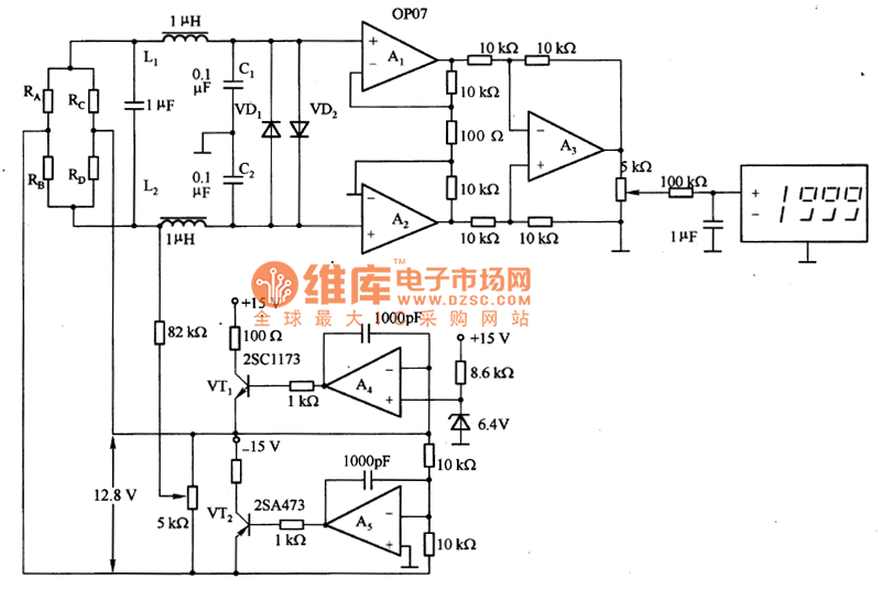
Digital display pressure measuring circuit diagram
The figure illustrates a digital display pressure measuring circuit diagram. The circuit operates with an additional voltage of approximately 12.8V and draws a current of 30mA. Under maximum gain conditions, the input voltage range is 0.8mV. The zero adjustment range...
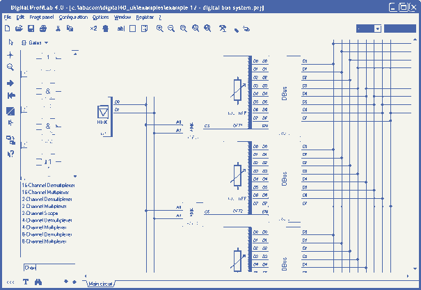
Digital-ProfiLab 4.0
Digital-ProfiLab was designed for measurement and control applications, combining features like circuit and logic simulation, front panel design, and hardware control to one powerful tool. Incoming signals from external devices may be processed and displayed. A circuit editor is used...
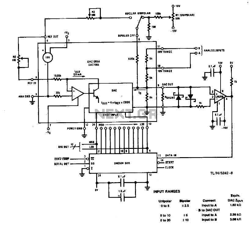
High Speed A/D converter 12-bit
This system performs a complete conversion of 12 bits in both unipolar and bipolar modes. The converter is accurate to ±12-bit LSB with a typical gain temperature coefficient of 10 ppm/°C. In unipolar mode, the system operates within a range...
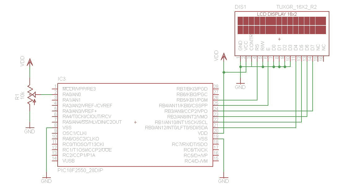
A/D converter 16Bit with LCD and PIC18F2550
The analog to digital converter (ADC) is commonly required in most of the projects. Analog voltage measurement can be done using the ADC hardware built in together in a PIC. The picture below shows a simple setup for measuring the...