


el cheapo cable tester
#cable tester
#multimeter
#voltage measurement
#9V battery
#resistors
#connectors
#simple circuit
#DIY
#electronics testing
#cheap solution
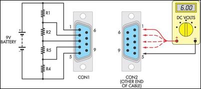
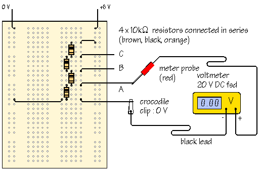
Description: Many cable testers have been previously published, some of which are quite complex. However, here is a cost-effective and straightforward alternative. It utilizes only a 9V battery, two mating connectors, and several resistors, along with a multimeter for voltage measurements. Start by soldering the leads of a 9V battery clip between the two pins that are furthest apart on one of the test connectors. Next, add a ladder of resistors between them for each of the other required pins. Any resistors from a junk box can be used, but values ranging from 1kΩ to 50kΩ are optimal. In the provided example, a five-core data cable terminated with D-9 connectors is to be tested. Connect 0V to pin 5, +9V to pin 1, and four resistors in between. Insert a 9V battery and then use a multimeter to probe the connector at the opposite end of the cable as indicated. Broken, shorted, or incorrect connections can be quickly identified using this method.
The cable tester circuit operates on a simple principle of voltage division and continuity checking. The circuit is designed to test the integrity of connections within a cable by utilizing a series of resistors to create a voltage divider network. Each resistor in the ladder corresponds to a specific pin in the connector, allowing for individual pin testing.
To construct the tester, the following components are necessary: a 9V battery, two D-9 connectors (or any other suitable connectors), a selection of resistors (preferably between 1kΩ and 50kΩ), and a multimeter. The battery clip is soldered to the two pins on one of the connectors, establishing the power source for the circuit. The resistors are connected in series between the power and ground connections, with each resistor leading to a different pin on the connector.
When testing a cable, the user connects the cable under test to the second D-9 connector. By applying the 9V battery and measuring the voltage at the corresponding pins on the opposite connector with a multimeter, it is possible to determine the condition of each connection. A reading close to 9V at a pin indicates a good connection, while a significantly lower voltage suggests a potential issue such as a short circuit, open circuit, or incorrect wiring.
This method is particularly useful for troubleshooting and verifying the integrity of multi-core cables in various applications, providing a reliable and low-cost solution for cable testing.Many cable testers have been published before, some quite complex, but here`s a cheap and simple alternative. It uses only a 9V battery, two mating connecators and a few resistors, as well as a multimeter for voltage measurements.
Begin by soldering the leads of a 9V battery clip between the two pins furthest apart on one of the test connectors an d then add a ladder of resistors between them for each of the other required pins. Any junk-box resistors will do but values between 1k © and 50k © are best. In the example shown, a five-core data cable terminated with D-9 connectors is to be tested. Connect 0V to pin 5, +9V to pin 1, and four resistors in between. Plug in a 9V battery and then probe the connector at the other end of the cable with a multimeter as indicated. Broken, shorted or incorrect connections are all quickly evident using this method.
The cable tester circuit operates on a simple principle of voltage division and continuity checking. The circuit is designed to test the integrity of connections within a cable by utilizing a series of resistors to create a voltage divider network. Each resistor in the ladder corresponds to a specific pin in the connector, allowing for individual pin testing.
To construct the tester, the following components are necessary: a 9V battery, two D-9 connectors (or any other suitable connectors), a selection of resistors (preferably between 1kΩ and 50kΩ), and a multimeter. The battery clip is soldered to the two pins on one of the connectors, establishing the power source for the circuit. The resistors are connected in series between the power and ground connections, with each resistor leading to a different pin on the connector.
When testing a cable, the user connects the cable under test to the second D-9 connector. By applying the 9V battery and measuring the voltage at the corresponding pins on the opposite connector with a multimeter, it is possible to determine the condition of each connection. A reading close to 9V at a pin indicates a good connection, while a significantly lower voltage suggests a potential issue such as a short circuit, open circuit, or incorrect wiring.
This method is particularly useful for troubleshooting and verifying the integrity of multi-core cables in various applications, providing a reliable and low-cost solution for cable testing.Many cable testers have been published before, some quite complex, but here`s a cheap and simple alternative. It uses only a 9V battery, two mating connecators and a few resistors, as well as a multimeter for voltage measurements.
Begin by soldering the leads of a 9V battery clip between the two pins furthest apart on one of the test connectors an d then add a ladder of resistors between them for each of the other required pins. Any junk-box resistors will do but values between 1k © and 50k © are best. In the example shown, a five-core data cable terminated with D-9 connectors is to be tested. Connect 0V to pin 5, +9V to pin 1, and four resistors in between. Plug in a 9V battery and then probe the connector at the other end of the cable with a multimeter as indicated. Broken, shorted or incorrect connections are all quickly evident using this method.
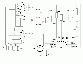
Basic Multimeter Circuit
A series of shunts and multipliers selected by a switch can be utilized in conjunction with a single basic meter to create a multirange instrument, commonly referred to as a multimeter. This device is capable of measuring voltage, current, and...
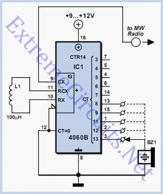
Simple Oscillator / Pipe Locator
Occasionally, there is a requirement to create a very basic oscillator. The circuit illustrated here is remarkably straightforward, utilizing only three components.
The described oscillator circuit typically consists of a resistor, a capacitor, and a single transistor. The operation of this...
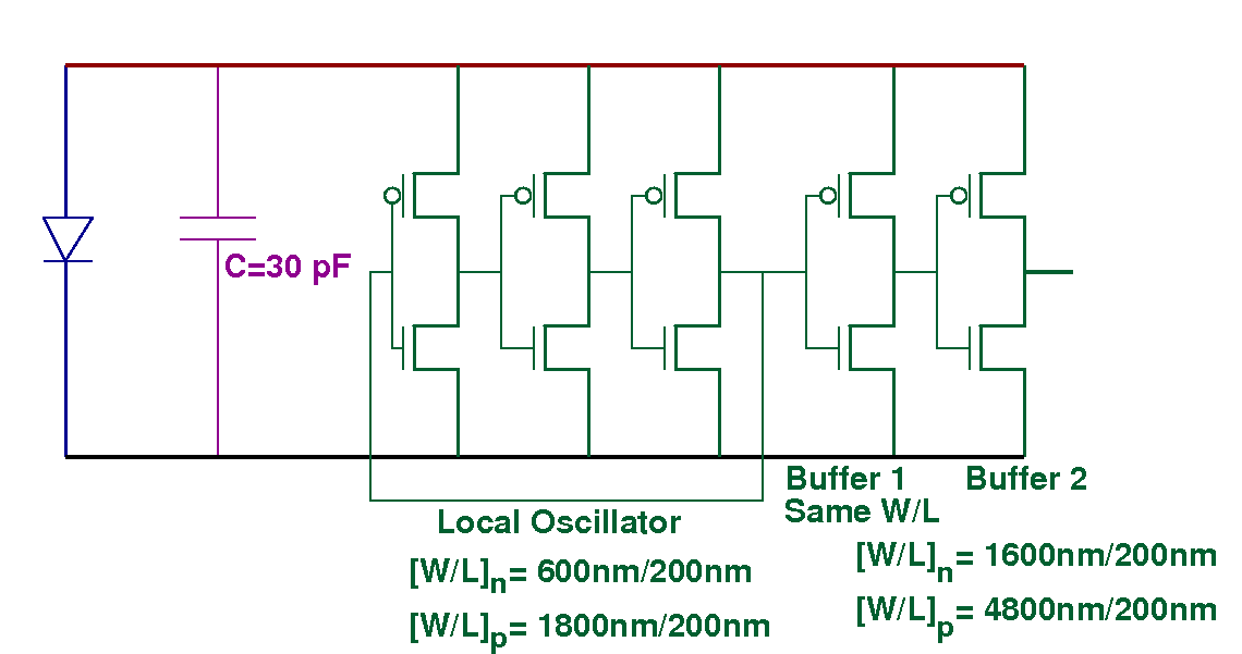
The Measurements for MIT 3DL1 Run
The chips that are classified as "working well" produce approximately 300 mV when exposed to a laser pointer and between 40 to 80 mV when illuminated by LED light. Voltages around 100 mV were recorded in a sunlit environment, while...
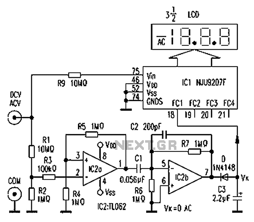
Multimeter AC DC converter circuit diagram automatically
The circuit depicted in the figure illustrates an automatic AC/DC converter for a digital multimeter. Typically, standard digital multimeters require manual intervention to switch between AC and DC measurements. The new DT860D digital multimeter utilizes the NJU9207F automatic range switching...
using a multimeter
A meter is a measuring instrument. An ammeter measures current, a voltmeter measures the potential difference (voltage) between two points, and an ohmmeter measures resistance. A multimeter combines these functions, and possibly some additional ones, into a single instrument. Before...
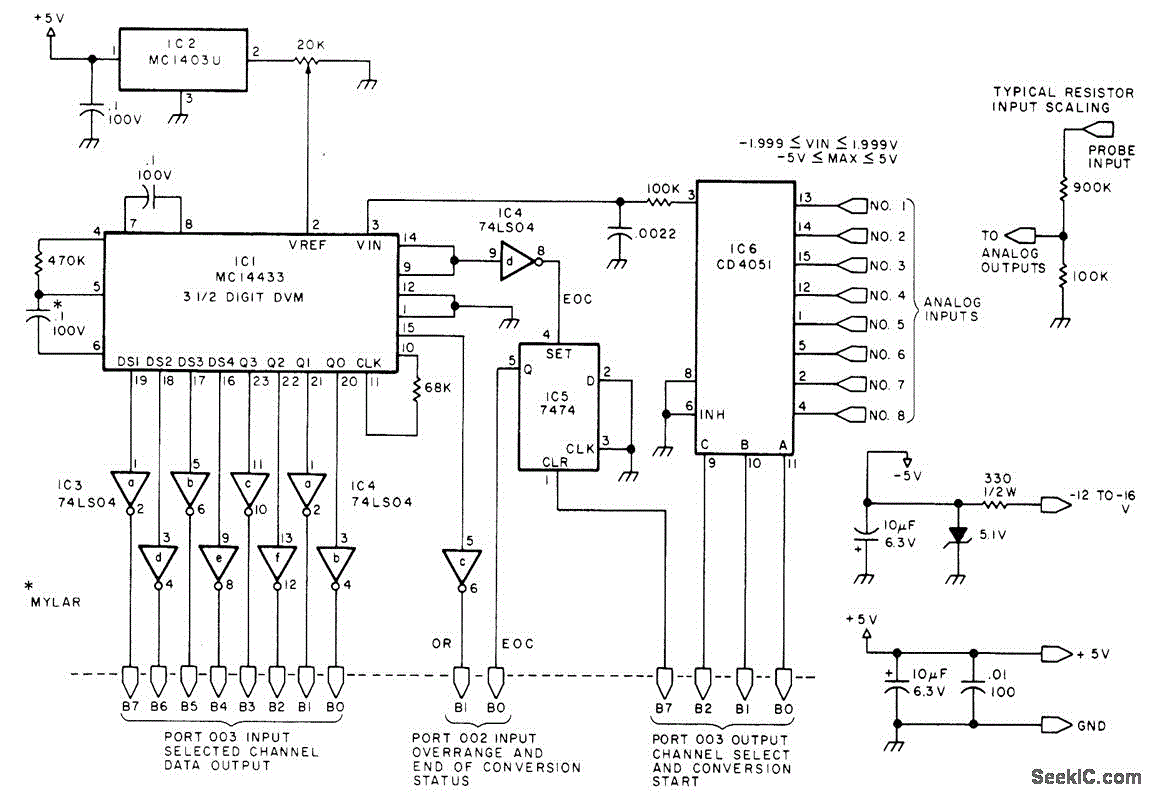
EIGHT CHANNEL COMPUTERIZED 3SUP1 SUP SUB2 SUB DIGIT_VM
Displays up to eight different DC voltages on a CRT terminal of a microprocessor under keyboard control, using BASIC commands and a BASIC routine provided in the article. Utilizes a modified Motorola MC14433 dual-lamp integrating analog-to-digital converter. An unknown voltage...
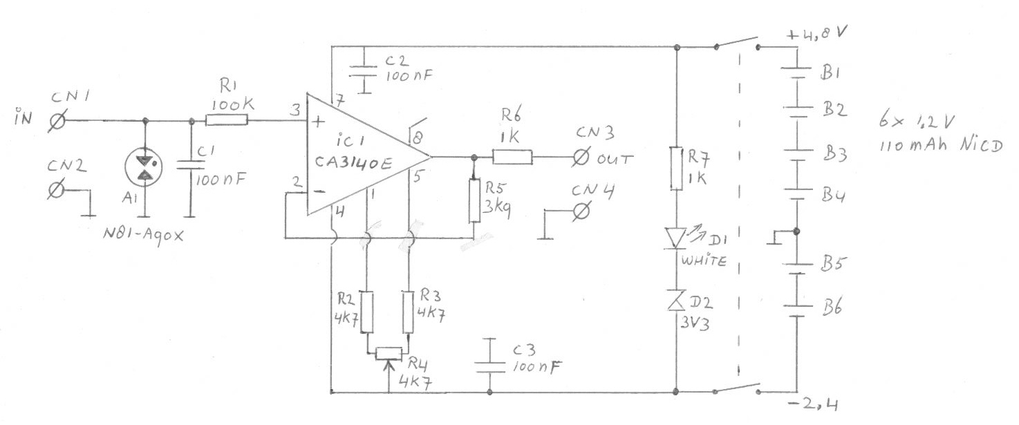
Coulomb meter
Another cause of voltage drift is the input current of IC1, which slowly charges capacitor C1. This effect is particularly noticeable when the output voltage is approximately 0 volts.
The circuit in question involves an integrated circuit (IC1) whose input current...
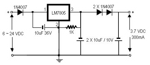
how to convert a 9v battery to 3.7v
A regulator circuit is needed for this DIY project. Familiarity with electronic components, circuitry, the use of a multitester, and a soldering iron is essential. The schematic diagram provided can accept an input voltage ranging from 6 to 24 volts...
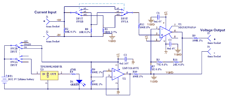
µCurrent Adaptor for multimeters
The µCurrent is in many cases also able to improve upon your meters current range accuracy by using your meters more accurate mVDC or mVAC voltage ranges instead to display the DC or AC current. With AC the frequency response...