


Exploring a digital I2C/SPI accelerometer (MMA7456L) with Bus Pirate
#accelerometer
#I2C
#SPI
#Bus Pirate
#sensor
#Freescale
#MMA7456L
#PC interface
#data acquisition
#embedded systems
Description: The Bus Pirate is an effective tool for exploring new chips with a PC, eliminating the need for integration into a microcontroller project. Upon receiving the unit, testing it with the MMA7456L accelerometer featuring an I2C/SPI interface from Freescale was undertaken. This article aims to assist others in getting started with the Bus Pirate and the I2C protocol specifically. The focus will be on the I2C interface, although the Bus Pirate offers much more functionality. Setting up the Bus Pirate is straightforward; it involves connecting to a USB port and installing the FTDI driver if required. It will then be recognized as a virtual COM port on the computer, allowing interaction through a terminal of choice. To identify the correct port, unplugging the device, checking the list of ports, and reconnecting it will reveal the new port corresponding to the Bus Pirate. The COM port list can be accessed via Device Manager on Windows or the Termite settings menu.
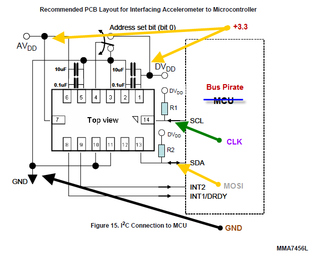
Using the probe cable accessory, connections were made on a breadboard according to the MMA7456L datasheet schematic, requiring only four Bus Pirate probes connected to the accelerometer. The accelerometer was mounted on a self-made breakout board, with a detailed tutorial available for SMT mounting and board etching in the article "DIY Surface Mount on a Budget: Complete Walkthrough from PCB Etching to Reflow." It is crucial to include pull-up resistors (10K) on each bus line to pull up the SDA and SCL lines, as indicated by resistors R1 and R2 in the schematic. Alternatively, the Bus Pirate's pull-up feature can be utilized instead of external resistors by connecting the Vpu pin to a voltage source (3.3V) and entering the command 'p' to enable the pull-up feature. For stability, the IADDR0 pin (3) should be grounded; the schematic includes a switch that allows for changing the default address of the device, which is unnecessary for this experiment. It was later observed that using the Bus Pirate's internal pull-up feature (with Vpu connected to 3.3V) caused issues when disconnecting oscilloscope probes. The oscilloscope probes, having 18-22pF capacitors, helped eliminate some noise. To mitigate noise from the computer power supply when operating at 100kHz, two 18pF capacitors were added between the SDA/SCL pins and ground, restoring functionality.
After completing the hardware setup, the next step involves using the Bus Pirate interface. A reset command should be sent, and the firmware/hardware version checked. Commands are issued in the Bus Pirate by typing '#' followed by Enter. It is important to note the version in use, as different versions may arise over time, potentially leading to variations in functionality or command structure.Bus Pirate is a great tool for exploring new chips using your PC, without the need to integrate the chip into a MCU project. Once I received my unit, i decided to put it to the test by exploring an accelerometer with I2C/SPI interface the MMA7456L from Freescale.
I am writing this in hope that it will help other people get started with BusPir ate and I2C protocol in particular. I will only describe the I2C interface in this article but BusPirate is capable of so much more ! The setup of BusPirate was simple. Simply plug it to your USB port, install the FDTI driver (if necessary). After that it will appear as a virtual COM port on you computer. You then can use your terminal of choice to interact with it. Here is sample session in Termite (my choice of terminal software): You will have to figure out which port your BusPirate is on. If you can`t figure it out, unplug it, observe list of ports, then plug it back to see which new port appeared that`s the one.
List of COM ports can be found in Device Manager on Windows or in Termite Settings menu. Other COM settings are as follows: Using the probe cable accessory, I did all connections on a breadboard guided by the schematic from MMA7456L datasheet. You will need just 4 Bus Pirate probes connected to the accelerometer. Below I am showing which ones and where you should connect them: Second thing to note is that my accelerometer was mounted on a breakout board I made myself, I have a detailed tutorial how you can do SMT mounting and etch your own boards in my article "DIY Surface Mount on a Budget Complete Walkthrough from PCB etching to Reflow", check it out Third thing don`t forget the the pull-up resistors (10K) on each bus line.
It is required to pull-up the SDA and SCL lines (see resistors R1 and R2 on schematic). You can also try the BP pullup feature instead of external resistors. The BusPirate on-board 10K pull-up resistors can be connected to the bus pins, by connecting Vpu pin to a volate pin (3. 3V), and then entering the p command to turn the pull-up feature on. However for stability you should ground the IADDR0 pin (3), on schematic they show a switch that allows a position where you can change the default address of the device.
We won`t need the switch for this experiment. I later discovered that while using the BusPirate internal pull-up feature (Vpu connected to 3. 3V), after I disconnect the oscilloscope probes the setup was no longer working! It must be the noise on the bus I said to myself. Oscilloscope probes have 18-22pf capacitors that actually eliminate some noise. I encountered this phenomenon many times, so I knew what is going on. I simply added two 18pF capacitors between SDA/SCL pins and ground and I was back in business. The noise is coming most of all from my computer power supply, and while working at 100Khz it becomes an issue. Ok, so once done with the hardware part, moving on to the BusPirate interface. First send a reset command and check your firmware/hardware version. A command is sent in bus pirate by typing the command # followed by Enter. Now take note of the version I am using, if you`re reading this article in a year or two there might be other versions available, so if something doesn`t make sense, it might be because your have a different version of BusPirate.
Using the probe cable accessory, connections were made on a breadboard according to the MMA7456L datasheet schematic, requiring only four Bus Pirate probes connected to the accelerometer. The accelerometer was mounted on a self-made breakout board, with a detailed tutorial available for SMT mounting and board etching in the article "DIY Surface Mount on a Budget: Complete Walkthrough from PCB Etching to Reflow." It is crucial to include pull-up resistors (10K) on each bus line to pull up the SDA and SCL lines, as indicated by resistors R1 and R2 in the schematic. Alternatively, the Bus Pirate's pull-up feature can be utilized instead of external resistors by connecting the Vpu pin to a voltage source (3.3V) and entering the command 'p' to enable the pull-up feature. For stability, the IADDR0 pin (3) should be grounded; the schematic includes a switch that allows for changing the default address of the device, which is unnecessary for this experiment. It was later observed that using the Bus Pirate's internal pull-up feature (with Vpu connected to 3.3V) caused issues when disconnecting oscilloscope probes. The oscilloscope probes, having 18-22pF capacitors, helped eliminate some noise. To mitigate noise from the computer power supply when operating at 100kHz, two 18pF capacitors were added between the SDA/SCL pins and ground, restoring functionality.
After completing the hardware setup, the next step involves using the Bus Pirate interface. A reset command should be sent, and the firmware/hardware version checked. Commands are issued in the Bus Pirate by typing '#' followed by Enter. It is important to note the version in use, as different versions may arise over time, potentially leading to variations in functionality or command structure.Bus Pirate is a great tool for exploring new chips using your PC, without the need to integrate the chip into a MCU project. Once I received my unit, i decided to put it to the test by exploring an accelerometer with I2C/SPI interface the MMA7456L from Freescale.
I am writing this in hope that it will help other people get started with BusPir ate and I2C protocol in particular. I will only describe the I2C interface in this article but BusPirate is capable of so much more ! The setup of BusPirate was simple. Simply plug it to your USB port, install the FDTI driver (if necessary). After that it will appear as a virtual COM port on you computer. You then can use your terminal of choice to interact with it. Here is sample session in Termite (my choice of terminal software): You will have to figure out which port your BusPirate is on. If you can`t figure it out, unplug it, observe list of ports, then plug it back to see which new port appeared that`s the one.
List of COM ports can be found in Device Manager on Windows or in Termite Settings menu. Other COM settings are as follows: Using the probe cable accessory, I did all connections on a breadboard guided by the schematic from MMA7456L datasheet. You will need just 4 Bus Pirate probes connected to the accelerometer. Below I am showing which ones and where you should connect them: Second thing to note is that my accelerometer was mounted on a breakout board I made myself, I have a detailed tutorial how you can do SMT mounting and etch your own boards in my article "DIY Surface Mount on a Budget Complete Walkthrough from PCB etching to Reflow", check it out Third thing don`t forget the the pull-up resistors (10K) on each bus line.
It is required to pull-up the SDA and SCL lines (see resistors R1 and R2 on schematic). You can also try the BP pullup feature instead of external resistors. The BusPirate on-board 10K pull-up resistors can be connected to the bus pins, by connecting Vpu pin to a volate pin (3. 3V), and then entering the p command to turn the pull-up feature on. However for stability you should ground the IADDR0 pin (3), on schematic they show a switch that allows a position where you can change the default address of the device.
We won`t need the switch for this experiment. I later discovered that while using the BusPirate internal pull-up feature (Vpu connected to 3. 3V), after I disconnect the oscilloscope probes the setup was no longer working! It must be the noise on the bus I said to myself. Oscilloscope probes have 18-22pf capacitors that actually eliminate some noise. I encountered this phenomenon many times, so I knew what is going on. I simply added two 18pF capacitors between SDA/SCL pins and ground and I was back in business. The noise is coming most of all from my computer power supply, and while working at 100Khz it becomes an issue. Ok, so once done with the hardware part, moving on to the BusPirate interface. First send a reset command and check your firmware/hardware version. A command is sent in bus pirate by typing the command # followed by Enter. Now take note of the version I am using, if you`re reading this article in a year or two there might be other versions available, so if something doesn`t make sense, it might be because your have a different version of BusPirate.
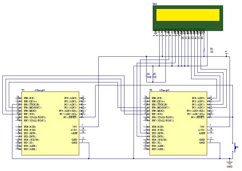
How to use SPI (Serial Peripheral Interface) in AVR Microcontrollers
SPI stands for Serial Peripheral Interface, which is the simplest among all communication protocols. Eight-bit data registers in the devices are connected by wires. These data registers function as shift registers, with one device controlling the data exchange within the...
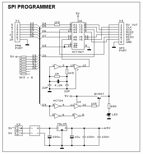
SPI-Flash Programmer 3.7
This SPI Flash Programmer can be utilized for both in-system programming and as a standalone serial flash programmer for Atmel SPI programmable devices. The hardware interface of the programmer is managed through the PC's parallel port, with control signals from...

SPI Interface Circuit for Big 7 Segment LED
This circuit is designed for general-purpose use with a large LED display utilizing SPI serial interfacing. It employs a serial-in-parallel-out shift register, specifically the 74HC595, to receive serial data from a microcontroller board. The schematic wiring indicates that SER is...
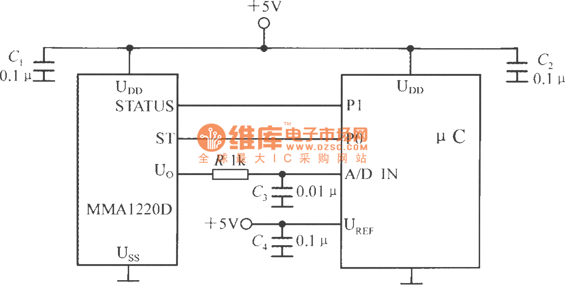
The interface circuit between single-chip accelerometer MMA1220D and microcontroller
The microcontroller within the A/D converter can utilize a PIC MCU produced by Microchip. The MMA1220D's state and self-test pins are connected to the P1 and P0 ports of the microcontroller, with its output voltage sent to the input of...

SAA1064
Each integrated circuit (IC) on the I²C bus requires a unique address. Typically, these ICs can choose from a range of 2 to 8 possible addresses, enabling multiple chips of the same type to coexist on a single bus. The...
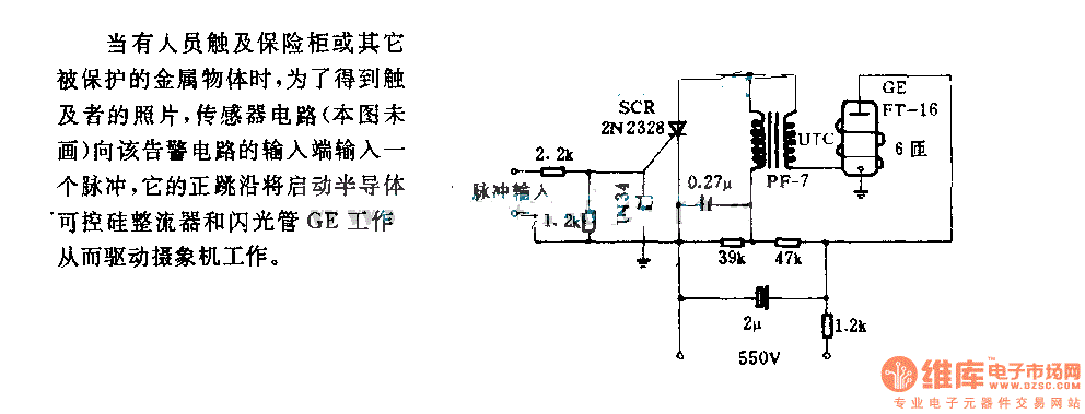
The alarm circuit diagram for safety box and other metal objects
When an individual touches the safety box or other protected metal objects, the sensor circuit generates a pulse to the alarm circuit. The positive edge of this pulse activates the semiconductor and thyristor flash GE, subsequently triggering the camera to...
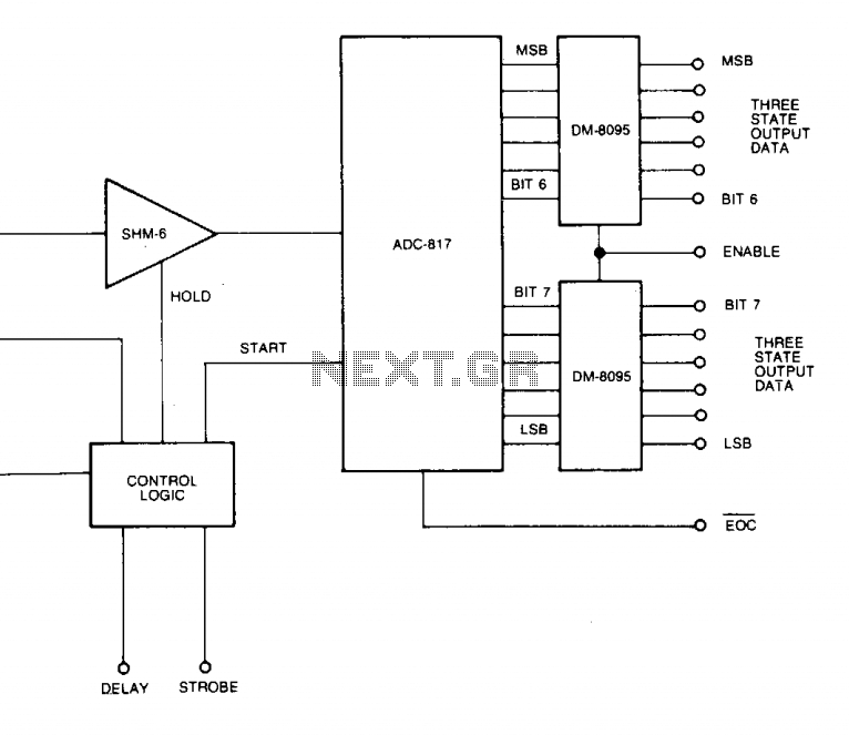
Fast data aquisition 2
A low-cost, high-speed monolithic analog multiplexer. The system operates by selecting a channel and initiating a conversion at a gain (G) of 1. It then examines the most significant bit (MSB) of the conversion result. If the MSB equals 1,...
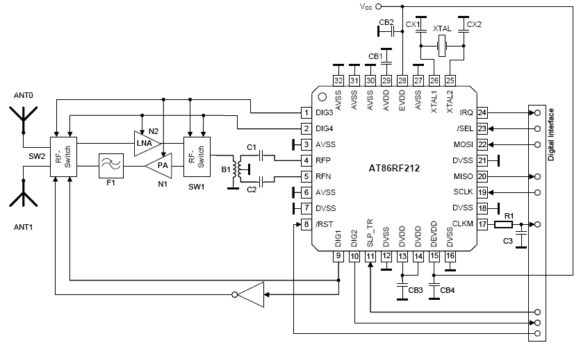
spi circuit
SPI Integrated Circuit Bus, IC Buses, an IC, Chip-to-Chip Bus Serial Peripheral Interface, Integrated Circuit Bus types, and IC Bus Electrical Interface Descriptions. The Peripheral Interface (SPI) circuit is a.
The Serial Peripheral Interface (SPI) is a synchronous serial communication protocol...
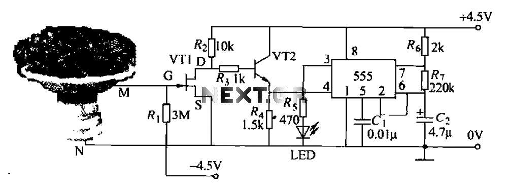
Pots water alarm circuit
The flowers in pots require watering, as relying solely on the observation of moist soil surfaces can be unreliable. To address this issue, a flower watering indicator has been developed. This circuit includes a field effect transistor (VT1), a second...