


Frequency comparator II
#frequency comparator
#PLL
#LED readout
#divider
#latch
#pulse counting
#measurement circuit
#precision
#frequency measurement
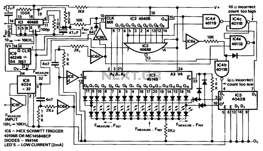
Description: The circuit provides a clear LED display indicating positive or negative values in increments of 0.1%. A reference frequency is generated by multiplying the input frequency using PLLIC1 and divider IC9, resulting in an output frequency of 64 times the reference frequency. This output is then processed by IC8, which divides the measured frequency by 32, establishing a relationship where the reference frequency equals the measured frequency. The counter IC2 counts up to 1024 pulses. If the count exceeds 1031, the latch IC4c/IC4a is activated to signal that the count is too high (measured frequency exceeds reference frequency). Conversely, if the count drops below 1017, IC3/IC4b indicates that the count is too low (measured frequency is less than reference frequency).
These signals are latched by IC5 at the end of each period, triggered by a latch signal from IC6e. When the two frequencies are within a tolerance of ±0.6%, the least significant bits (LSBs) of the counter IC2 are decoded and latched by IC7, which then displays the values on the LEDs. IC6c resets the counter following the data latching process.
The circuit operates by first establishing a reference frequency through a phase-locked loop (PLL) and a frequency divider. This reference frequency is crucial for accurate measurement and comparison against the incoming signal. The division of the measured frequency allows for a manageable range of values for the counter IC2, which is designed to handle up to 1024 pulses.
The use of latches (IC4a, IC4b, and IC5) ensures that the system can reliably capture and hold the state of the frequency measurements at specific intervals, allowing for a stable output on the LED display. The tolerance of ±0.6% is a critical design feature, ensuring that minor fluctuations in frequency do not result in erroneous readings. The decoding and display of the LSBs further enhance the usability of the circuit by providing a precise visual representation of the measured frequencies.
The reset function provided by IC6c is essential for preparing the counter for subsequent measurements, ensuring that each measurement cycle starts from a known state. Overall, the circuit is designed for precise frequency measurement and display, making it suitable for applications requiring accurate and real-time frequency analysis.The circuit provides unambiguous LED + or - bar readout with steps of 0.1%. The reference frequency is multiplied by the PLLIC1 and divider IC9 to output 64 ? F (ref) and this is then gated by dividing F (measure) by 32 in IC8 thus is F (ref) = (measure) then IC2 counts 1024 pulses. Should the count be more than 1031 than the latch IC4c/IC4a is set to indicate count too high (F (measure) F (ref)) and if the count is less than 1017 then IC3/IC4b indicate count too low (F (measure) F (ref).
These signals are latched by IC5 at the end of each period by the latch signal from IC6e. When the two frequencies are within + or - 0.6% the LSB's of the counter IC2 are decoded and latched by IC7 and displayed on LED's IC6c resets the counter after latching the data.
These signals are latched by IC5 at the end of each period, triggered by a latch signal from IC6e. When the two frequencies are within a tolerance of ±0.6%, the least significant bits (LSBs) of the counter IC2 are decoded and latched by IC7, which then displays the values on the LEDs. IC6c resets the counter following the data latching process.
The circuit operates by first establishing a reference frequency through a phase-locked loop (PLL) and a frequency divider. This reference frequency is crucial for accurate measurement and comparison against the incoming signal. The division of the measured frequency allows for a manageable range of values for the counter IC2, which is designed to handle up to 1024 pulses.
The use of latches (IC4a, IC4b, and IC5) ensures that the system can reliably capture and hold the state of the frequency measurements at specific intervals, allowing for a stable output on the LED display. The tolerance of ±0.6% is a critical design feature, ensuring that minor fluctuations in frequency do not result in erroneous readings. The decoding and display of the LSBs further enhance the usability of the circuit by providing a precise visual representation of the measured frequencies.
The reset function provided by IC6c is essential for preparing the counter for subsequent measurements, ensuring that each measurement cycle starts from a known state. Overall, the circuit is designed for precise frequency measurement and display, making it suitable for applications requiring accurate and real-time frequency analysis.The circuit provides unambiguous LED + or - bar readout with steps of 0.1%. The reference frequency is multiplied by the PLLIC1 and divider IC9 to output 64 ? F (ref) and this is then gated by dividing F (measure) by 32 in IC8 thus is F (ref) = (measure) then IC2 counts 1024 pulses. Should the count be more than 1031 than the latch IC4c/IC4a is set to indicate count too high (F (measure) F (ref)) and if the count is less than 1017 then IC3/IC4b indicate count too low (F (measure) F (ref).
These signals are latched by IC5 at the end of each period by the latch signal from IC6e. When the two frequencies are within + or - 0.6% the LSB's of the counter IC2 are decoded and latched by IC7 and displayed on LED's IC6c resets the counter after latching the data.

Keyless Lock
The circuit employs a four-bit latch (U1). The sequential nature of the circuit is established by connecting the set input of the first bit latch to the reset of the second bit latch, and this pattern continues for the subsequent...
PLL pulse generator(74HC4060 TC9122P)
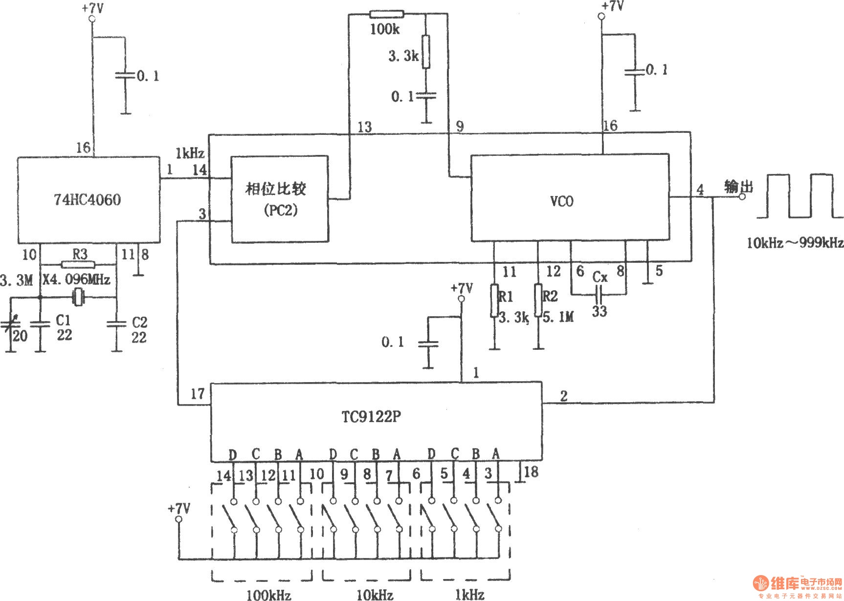
The PLL pulse generator is illustrated in the accompanying chart. The circuit represents a phase-locked loop (PLL) pulse generator. The PLL generates a fractional frequency from a crystal oscillator, producing a 1 kHz stepped frequency signal. Additionally, it outputs a...
voltage frequency synthesizer PLL
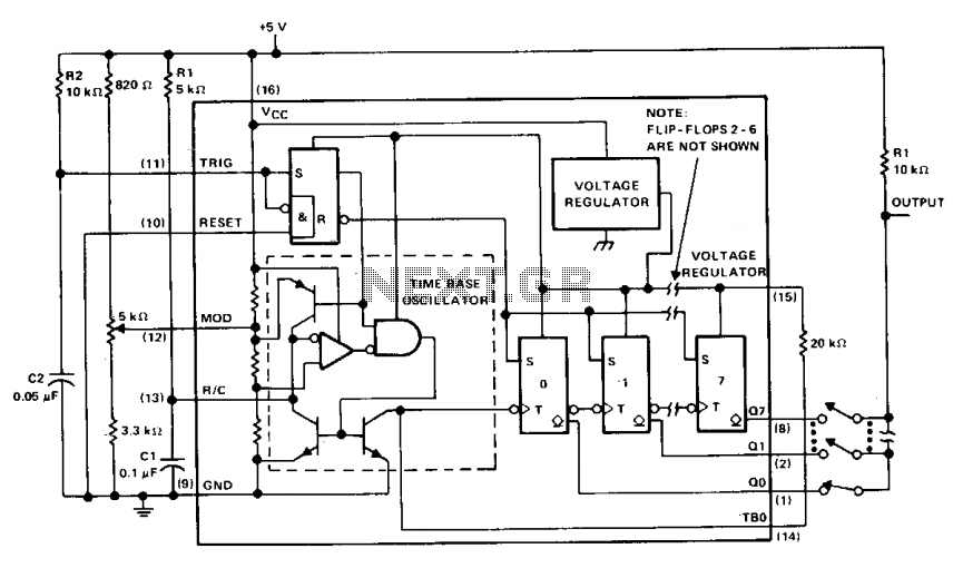
The µA2240 consists of four basic circuit elements: (1) a time-base oscillator, (2) an eight-bit counter, (3) a control flip-flop, and (4) a voltage regulator. The basic frequency of the time-base oscillator (TBO) is set by the external time constant...
Using the MC145158 PLL Frequency Synthesizer
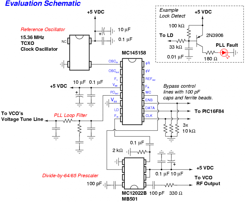
The Motorola MC145158 is a dual-modulus, serial-input PLL frequency synthesizer commonly utilized in older Motorola cellular phones. For detailed technical specifications, refer to the MC145158 datasheet. Although the MC145158 is no longer in production, it can occasionally be found in...
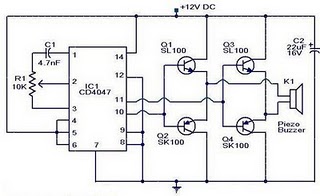
Electronic mosquito repeller circuit diagram
The circuit operates on the principle that insects, such as mosquitoes, can be repelled using sound frequencies in the ultrasonic range (above 20 kHz). It utilizes a Phase-Locked Loop (PLL) integrated circuit, specifically the CMOS 4047, configured as an oscillator...
PLL pulse generator(74HC4060 TC9122P)
The PLL pulse generator is illustrated in the accompanying chart. The circuit represents a phase-locked loop (PLL) pulse generator. The PLL generates a fractional frequency from a crystal oscillator, producing a 1 kHz stepped frequency signal. Additionally, it outputs a...
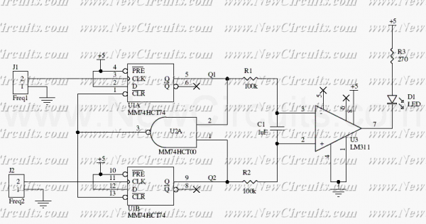
2 Input Pulses Frequency Comparator
This circuit uses a 74HCT74, 74HCT00, and a LM311 to form a frequency comparator. The two pulse trains are fed to two D-type flip-flops (triggered by the leading edges). The flip-flops' outputs are compared in a NAND gate. If the...
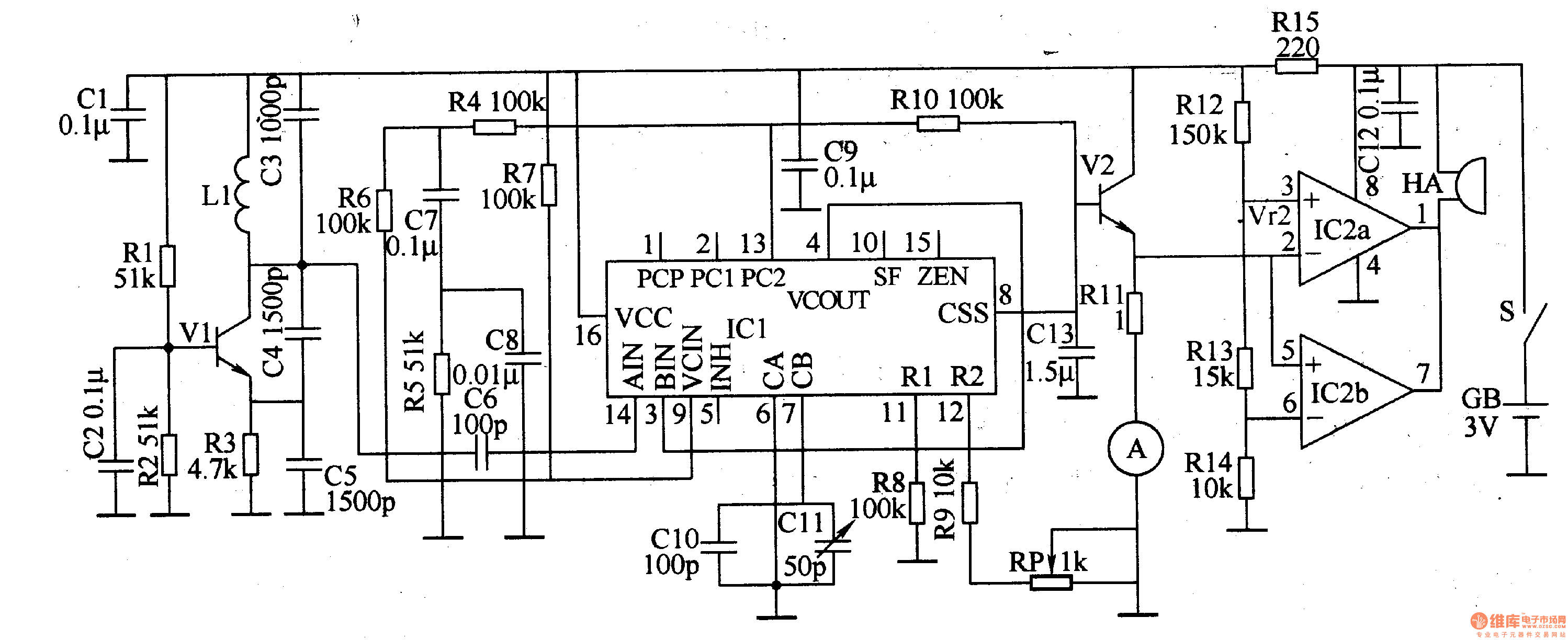
Metal detector 8
This example describes a metal detector that employs a PLL (phase-locked loop) digital integrated circuit, the MCl4046. It emits an alarm signal upon detecting metal objects and can identify the type of detected material based on the current meter's readings....
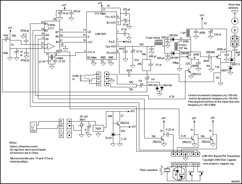
PLL FM Transmitter using LMX1601 ATtiny2313 AT90S2313
This document describes a PLL FM transmitter utilizing the LMX1601 and either the ATtiny2313 or AT90S2313 microcontrollers. A common feature of previous low-power FM transmitters developed over the years is that their operating frequency is determined by an LC resonant...