


GPS-Disciplined 10 MHz Frequency Standard / GPS-Based Universal Time Clock
#GPS
#frequency standard
#crystal oscillator
#phase-locked-loop
#precision timing
#10 MHz
#10 kHz
#1 Hz
#time clock
#PLL
Description: The block diagram illustrates that a 10 MHz signal is generated by an oven-stabilized 10 MHz crystal oscillator, which is locked to a precision 10 kHz signal produced by a GPS receiver module through a phase-locked-loop (PLL) circuit. In addition to the 10 MHz signal, the system also outputs precision 10 kHz and 1 Hz signals. The 1 Hz signal serves as a precise pulse-per-second reference for clocks that can utilize such input. The raw NMEA data from the GPS receiver is transmitted to an RS-232 level converter and a PIC microcontroller. The PIC decodes the data to display accurate location and universal time information. The RS-232 data is relayed to various instruments capable of utilizing it, such as for precision satellite tracking with a space-communications antenna array. The GPS receiver utilized is a surplus OEM unit produced by Rockwell. However, any GPS module that provides a GPS-derived 10 kHz signal can be employed. The PLL circuit, designed by Joe Ruggieri, is constructed on a circuit board available for purchase. This circuit connects directly to the 10 MHz OCXO and the 10 kHz output from the GPS module. It operates on a 12 VDC supply, sourced from an external power supply. The performance of the GPS-disciplined oscillator is exceptional, as indicated by comparisons with the output of a rubidium atomic clock reference.
The electronic schematic described involves several critical components working in concert to produce stable frequency outputs. The primary component is the oven-controlled crystal oscillator (OCXO), which serves as the main frequency source, generating a stable 10 MHz signal. The PLL circuit locks this oscillator to the 10 kHz signal derived from the GPS module, enhancing frequency accuracy and stability. The GPS module, which can be any compatible unit that provides a 10 kHz output, plays a pivotal role in maintaining synchronization with global time standards.
The RS-232 level converter is essential for interfacing the GPS output with the PIC microcontroller, ensuring that the data format is compatible for processing. The PIC microcontroller decodes the NMEA data, which contains vital information such as geographic coordinates and universal time. This data can be displayed on a user interface or sent to other devices for further applications, including satellite tracking.
Powering the PLL circuit with a 12 VDC supply is necessary for its operation, ensuring that the PLL can maintain the frequency lock effectively. The design and construction of the PLL circuit by Joe Ruggieri provide a reliable solution for achieving the desired frequency stability and precision.
Overall, this system exemplifies the integration of various electronic components to achieve high-performance timekeeping and navigation capabilities, leveraging both crystal oscillator technology and GPS-derived signals for enhanced accuracy in timing applications.As shown in the block diagram above, the 10 MHz signal is produced by an oven-stabilized 10 MHz crystal oscillator that is locked by a phase-locked-loop circuit (PLL) against the precision 10 kHz signal generated by the GPS receiver module. In addition to the 10 MHz signal, precision 10 kHz and 1 Hz signals are also output by the system. The 1 Hz signal is especially useful as a precise 1 pulse-per-second reference for clocks that can accept such input. The raw NMEAdata generated by the GPS receiver is sent to a RS-232 level converter and to a PIC microcontroller. The PIC decodes the data and displays exact location and universal time information. The RS232data are sent to instruments around my shack that can use it, for example for precision satellite tracking with my space-communications antenna array.
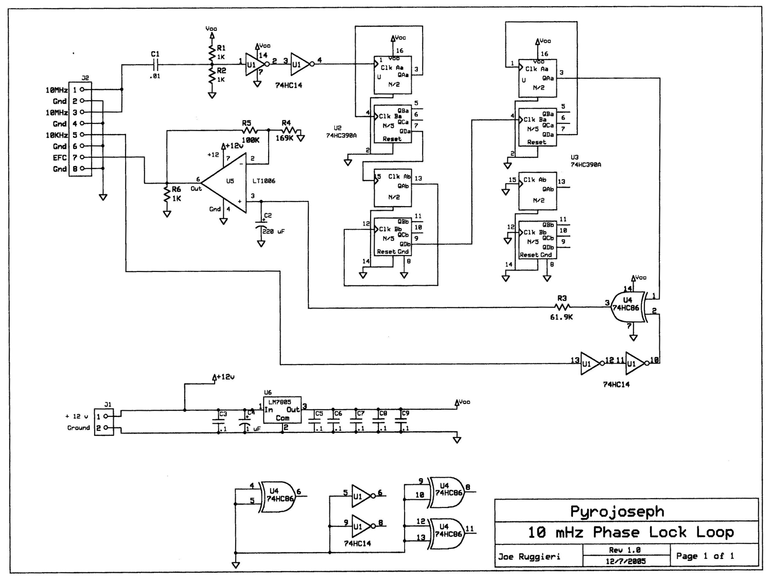
The GPS receiver that I used is a surplusOEM unit made by Rockwell (information available here: Rockwell_Jupiter_GPS ). However, any other GPS module that outputs a GPS-derived 10 kHz signal may be used. The PLLcircuit (click on the figure to enlarge)was designed by Joe Ruggieri(AKA eBay Pyrojoseph) and constructed on a circuit board that he sells.
The circuit connects directly to the 10 MHz OCXO and to the 10 kHz output from the GPS module. The circuit requires 12 VDC, which I feed from an external power supply. As shown in the following figure, the GPS-disciplined oscillator performs superbly as evidenced by comparing its output to that of my rubidium atomic clock reference :
The electronic schematic described involves several critical components working in concert to produce stable frequency outputs. The primary component is the oven-controlled crystal oscillator (OCXO), which serves as the main frequency source, generating a stable 10 MHz signal. The PLL circuit locks this oscillator to the 10 kHz signal derived from the GPS module, enhancing frequency accuracy and stability. The GPS module, which can be any compatible unit that provides a 10 kHz output, plays a pivotal role in maintaining synchronization with global time standards.
The RS-232 level converter is essential for interfacing the GPS output with the PIC microcontroller, ensuring that the data format is compatible for processing. The PIC microcontroller decodes the NMEA data, which contains vital information such as geographic coordinates and universal time. This data can be displayed on a user interface or sent to other devices for further applications, including satellite tracking.
Powering the PLL circuit with a 12 VDC supply is necessary for its operation, ensuring that the PLL can maintain the frequency lock effectively. The design and construction of the PLL circuit by Joe Ruggieri provide a reliable solution for achieving the desired frequency stability and precision.
Overall, this system exemplifies the integration of various electronic components to achieve high-performance timekeeping and navigation capabilities, leveraging both crystal oscillator technology and GPS-derived signals for enhanced accuracy in timing applications.As shown in the block diagram above, the 10 MHz signal is produced by an oven-stabilized 10 MHz crystal oscillator that is locked by a phase-locked-loop circuit (PLL) against the precision 10 kHz signal generated by the GPS receiver module. In addition to the 10 MHz signal, precision 10 kHz and 1 Hz signals are also output by the system. The 1 Hz signal is especially useful as a precise 1 pulse-per-second reference for clocks that can accept such input. The raw NMEAdata generated by the GPS receiver is sent to a RS-232 level converter and to a PIC microcontroller. The PIC decodes the data and displays exact location and universal time information. The RS232data are sent to instruments around my shack that can use it, for example for precision satellite tracking with my space-communications antenna array.
The GPS receiver that I used is a surplusOEM unit made by Rockwell (information available here: Rockwell_Jupiter_GPS ). However, any other GPS module that outputs a GPS-derived 10 kHz signal may be used. The PLLcircuit (click on the figure to enlarge)was designed by Joe Ruggieri(AKA eBay Pyrojoseph) and constructed on a circuit board that he sells.
The circuit connects directly to the 10 MHz OCXO and to the 10 kHz output from the GPS module. The circuit requires 12 VDC, which I feed from an external power supply. As shown in the following figure, the GPS-disciplined oscillator performs superbly as evidenced by comparing its output to that of my rubidium atomic clock reference :
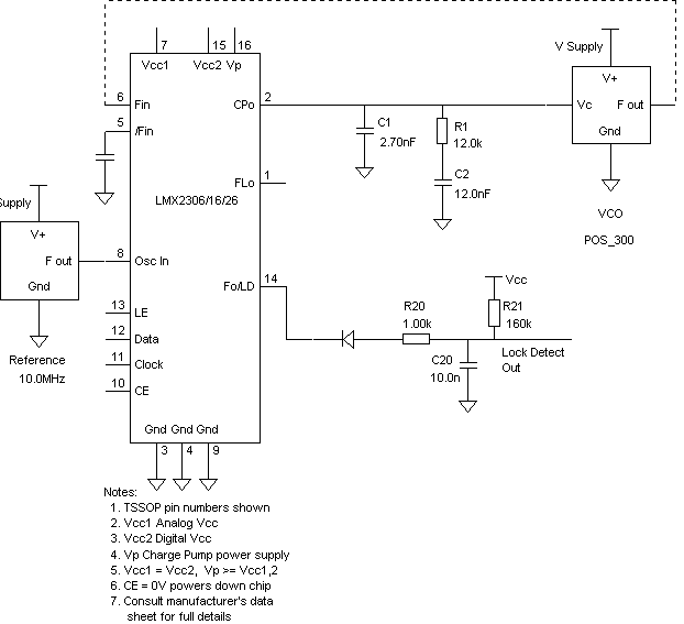
150MHz to 170MHz in 25kHz steps using a LMX2306 PLL
Using SimPLL's new PLL Wizard, a new Phase-Locked Loop (PLL) can be designed with just a few clicks. A PLL has been designed that tunes from 150 MHz to 170 MHz in 25 kHz steps, utilizing the LMX2306 PLL integrated...
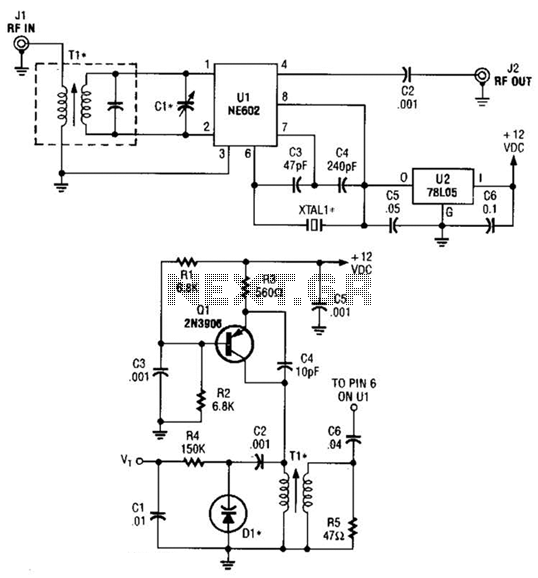
One-Chip Crystal-Controlled Converter Circuit
This circuit operates effectively across a broad frequency spectrum. XTAL 1 serves as a fundamental-frequency crystal. Tl and CI are adjusted to match the input frequency. This circuit can be utilized as a straightforward shortwave converter for AM radios, among...
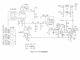
PLL Synthesizer for 150 MHz Local Oscillator
This MOT's LSI is highly suitable for designing VFOs in ham radios, featuring a 4-digit BCD preset counter with a range from 3 to 3999. It also includes a standard crystal frequency oscillator and preset dividers. The input nodes of...
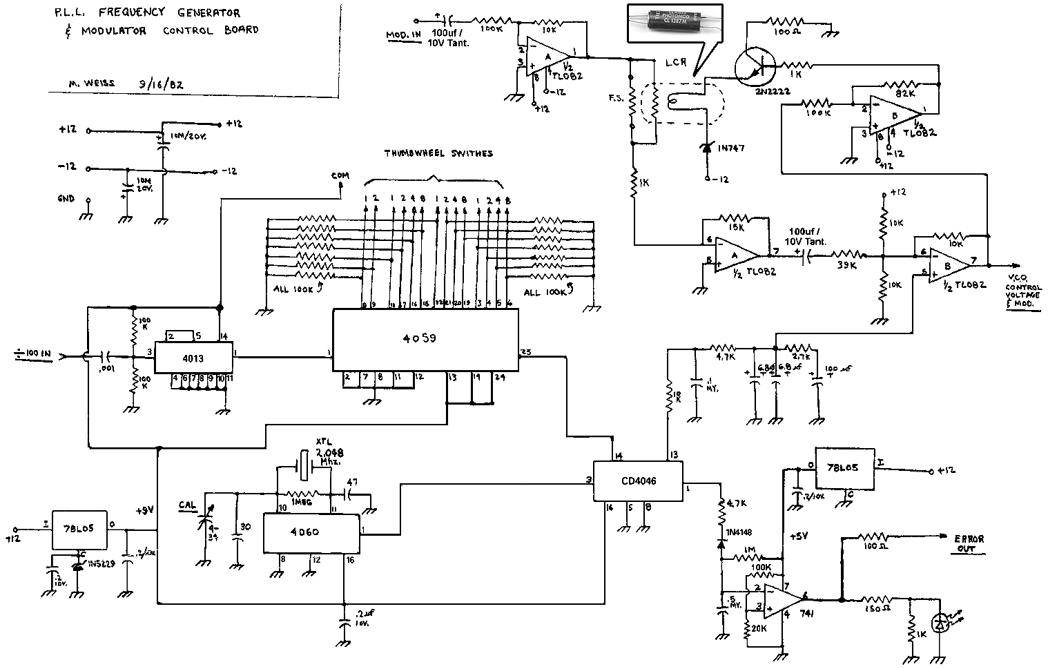
PLL Exciter-2
This is a Phase-Locked Loop (PLL) controller designed to operate with a Voltage-Controlled Oscillator (VCO) and modulator. These two modules should be utilized together to create a complete baseband-capable exciter unit. The PLL controller incorporates a stable crystal-controlled reference and...
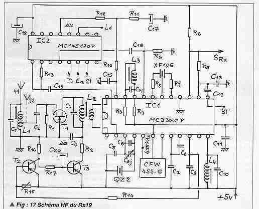
PLL 41MHz reciever with 68HC711D3
The quartz QZ1 of the preceding receivers which set the work frequency is not on the market any more. It is replaced by a locking phase loop allowing the free choice of an unspecified frequency on the band used, either...
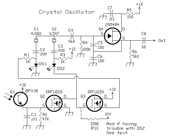
Circuit Crystal Oscillator/Amplifier
This oscillator is a variation of the oscillator presented by Ulrich L. Rohde, DJ2LR, in his article "Evaluating Noise Sideband Performance in Oscillators," published in Ham Radio, October 1978, Page 51. The original circuit can be found at the bottom...
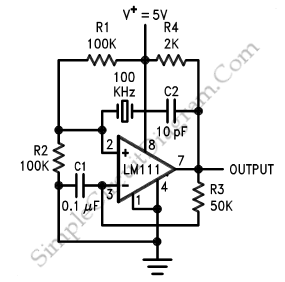
Crystal Oscillator
A crystal oscillator, particularly a low-frequency variant, can be effectively constructed using an operational amplifier (op-amp) as the amplification component. Below is the schematic diagram of this circuit.
The crystal oscillator circuit utilizes the properties of a quartz crystal to generate...
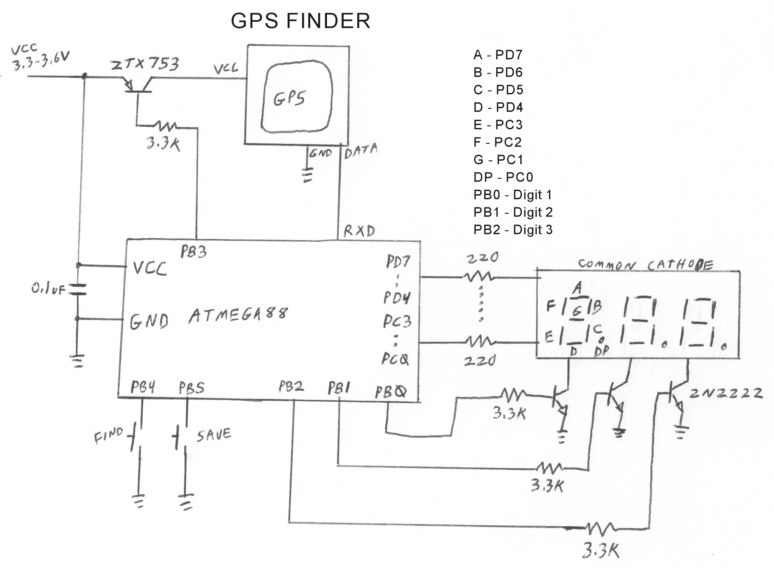
The Finder
The Finder is a prototype GPS device designed to be keychain-sized, featuring two buttons labeled "Save" and "Find." The "Save" button records the current location, while the "Find" button guides the user back to the saved location. Up to nine...
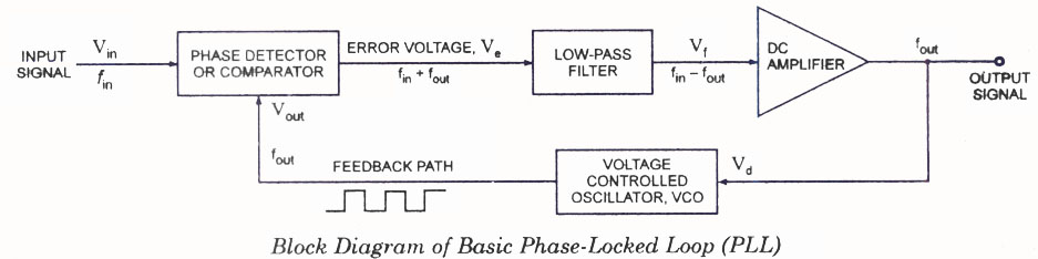
Phase Locked Loop (PLL) Operating Principle Phase Detector VCO LPF
The operating principle of a Phase Locked Loop (PLL) is illustrated with a block diagram that includes a Phase Detector, Voltage Controlled Oscillator, and Low Pass Filter.
A Phase Locked Loop (PLL) is an essential electronic circuit used in various applications...