


High-Speed Photos of Low-Speed Impacts
#high-speed photography
#timing circuit
#sensor
#trigger
#digital camera
#electronics
#DIY
#freeze motion
#photography
#experimental
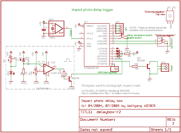
Description: The objective is to capture various stages of a rapid process, especially in comparison to the resolution of the human eye. Due to the lack of advanced equipment such as a high-speed film camera, a practical setup utilizing a standard consumer digital camera and custom electronics is required. The camera's minimum exposure time of approximately 1 millisecond is inadequate, and there is a significant delay of about one second between pressing the shutter button and the actual opening of the shutter. The proposed method involves creating a dark environment, opening the camera shutter, dropping a ball, igniting a photo flash after a predetermined delay, and then closing the shutter. This approach allows the exposure time to be defined by the duration of the photo flash, which has been measured to be less than 100 microseconds when appropriately configured.
To ensure consistent drop points for the ball, a manual release is not feasible. Instead, a dropping mechanism utilizing an induction coil was developed, as steel balls are magnetic. The coil is wrapped in white paper for visibility. When the current through the coil is turned off, the ball is released. To mitigate sparks and high voltage spikes, an RC-damped MOSFET-based switch is employed to control the current through the coil gradually. However, the timing of the switch is not precise enough to serve as a start signal, thus a custom light barrier is implemented. This light barrier comprises an orange LED and a photodiode, with a lens positioned in front of the LED to focus the light. The interruption of light by the falling ball serves as the start signal. Following this event, the ball descends and eventually makes contact with sand, with the fall time typically in the range of several hundred milliseconds for drop heights below one meter.
A delay trigger has been designed to initiate upon receiving the start signal from the light barrier, wait for a specified duration, and then trigger the flash. The delay can be adjusted in increments of 500 microseconds using an impulse switch. The microcontroller's intrinsic accuracy, due to interrupt handling, is 4 microseconds, with the base clock maintaining a tolerance of less than 100 parts per million. Three LEDs connected to the microcontroller provide visual feedback indicating changes in delay when the switch is adjusted. Additionally, a JP3 connector is linked to a custom frequency counter to measure the actual delay time. An auto-increment mode is also available, allowing the microcontroller to automatically increase the delay by a fixed amount after each trigger event. The microcontroller operates with a self-developed firmware, written in C and compiled using avr-gcc, and is programmed via a USB-based Atmel programmer.
The schematic for this setup includes the following components:
1. **Digital Camera**: The primary imaging device, which requires control signals for shutter operation.
2. **Induction Coil**: Used to hold and release the steel ball, controlled by a MOSFET switch.
3. **MOSFET Switch**: An RC-damped switch to manage the current through the induction coil, preventing high voltage spikes.
4. **Light Barrier**: Comprising an orange LED and photodiode, used to detect the ball's drop and trigger the timing mechanism.
5. **Microcontroller**: Responsible for processing the start signal, managing the delay, and firing the flash. It includes a clock for timing precision and outputs for the LEDs and frequency counter.
6. **Impulse Switch**: A user interface component that allows for manual adjustment of the delay time.
7. **LED Indicators**: Provide visual feedback on the current delay setting.
8. **JP3 Connector**: For connecting to an external frequency counter to monitor timing accuracy.
The complete circuit is designed to ensure precise timing and synchronization between the camera shutter, the ball release, and the flash, enabling high-resolution capture of fast events.The goal is to freeze different stages of some fairly quick process (at least when compared to the time resulotion of the human eye). Since I don`t have fancy toys like a high speed film camera, lack of good equipment has to be compensated with a smart setup applying just a an ordinary consumer-type digital camera and some self-made electronics.
U nfortunately, the camera`s minimum exposure of about 1ms is too long for the purpose and furthermore the delay from pressing the button to actually opening the shutter is around a second - quite long. So, the basic idea is to make the complete room dark, open the shutter of the camera, drop the ball, ignite the photo flash after some time and close the shutter again.
This way the real exposure time is given by the duration of the photo flash which was measured by me (using a DSO) to be less than 100us (better than 1/10, 000 second) when set up accrodingly. So, first we need to hold the ball and make sure it falls down each time at the same point, so using one`s own hands is not an option.
Instead, since steel balls are magnetic, we built a dropping device made of an induction coil. (In the image on the right, white paper is wrapped around the coil. ) When switching off the current through the coil, the ball drops down. To prevent sparks and high voltage peaks, we were actually using a RC-damped MOSFET-based switch to slowly turn on/off the the current through the coil. Hence, using the switch time as start signal is not precise enough and a self-made light barrier was used.
The light barrier consists of a orange LED and a photo diode. In front of the LED, a lens was introduced to focus the light onto the LED. Light interruption by the ball is the start signal. After the start signal, some time passes during which the ball drops down and then finally touches the sand. This time is in the order of several 100ms for usual drop heights below 1m. I designed a delay trigger which will start running when the light barrier sends the start signal, wait some time and then fire the flash.
The time can be varied in steps of half a millisecond (500us) using an impulse switch ("Drehimpulsgeber"). The intrinisc accuracy of the microcontroller (due to interrupt handling) is 4us and the base clock has a tolerance of less than 100ppm.
The 3 LEDs connected to the microcontroller are a delay change indication for visual feedback when turning the switch. Additionally, the JP3 connector was connected to my self-made frequency counter to measure the actual delay time.
There is some additional comfort like a switch which will enable auto increment mode where the microcontroller will increase the delay automatically by a fixed amount after each trigger event. The microcontroller runs a self-developed firmware (written in C, compiled with avr-gcc) and was downloaded onto the controller using my USB-based Atmel programmer.
To ensure consistent drop points for the ball, a manual release is not feasible. Instead, a dropping mechanism utilizing an induction coil was developed, as steel balls are magnetic. The coil is wrapped in white paper for visibility. When the current through the coil is turned off, the ball is released. To mitigate sparks and high voltage spikes, an RC-damped MOSFET-based switch is employed to control the current through the coil gradually. However, the timing of the switch is not precise enough to serve as a start signal, thus a custom light barrier is implemented. This light barrier comprises an orange LED and a photodiode, with a lens positioned in front of the LED to focus the light. The interruption of light by the falling ball serves as the start signal. Following this event, the ball descends and eventually makes contact with sand, with the fall time typically in the range of several hundred milliseconds for drop heights below one meter.
A delay trigger has been designed to initiate upon receiving the start signal from the light barrier, wait for a specified duration, and then trigger the flash. The delay can be adjusted in increments of 500 microseconds using an impulse switch. The microcontroller's intrinsic accuracy, due to interrupt handling, is 4 microseconds, with the base clock maintaining a tolerance of less than 100 parts per million. Three LEDs connected to the microcontroller provide visual feedback indicating changes in delay when the switch is adjusted. Additionally, a JP3 connector is linked to a custom frequency counter to measure the actual delay time. An auto-increment mode is also available, allowing the microcontroller to automatically increase the delay by a fixed amount after each trigger event. The microcontroller operates with a self-developed firmware, written in C and compiled using avr-gcc, and is programmed via a USB-based Atmel programmer.
The schematic for this setup includes the following components:
1. **Digital Camera**: The primary imaging device, which requires control signals for shutter operation.
2. **Induction Coil**: Used to hold and release the steel ball, controlled by a MOSFET switch.
3. **MOSFET Switch**: An RC-damped switch to manage the current through the induction coil, preventing high voltage spikes.
4. **Light Barrier**: Comprising an orange LED and photodiode, used to detect the ball's drop and trigger the timing mechanism.
5. **Microcontroller**: Responsible for processing the start signal, managing the delay, and firing the flash. It includes a clock for timing precision and outputs for the LEDs and frequency counter.
6. **Impulse Switch**: A user interface component that allows for manual adjustment of the delay time.
7. **LED Indicators**: Provide visual feedback on the current delay setting.
8. **JP3 Connector**: For connecting to an external frequency counter to monitor timing accuracy.
The complete circuit is designed to ensure precise timing and synchronization between the camera shutter, the ball release, and the flash, enabling high-resolution capture of fast events.The goal is to freeze different stages of some fairly quick process (at least when compared to the time resulotion of the human eye). Since I don`t have fancy toys like a high speed film camera, lack of good equipment has to be compensated with a smart setup applying just a an ordinary consumer-type digital camera and some self-made electronics.
U nfortunately, the camera`s minimum exposure of about 1ms is too long for the purpose and furthermore the delay from pressing the button to actually opening the shutter is around a second - quite long. So, the basic idea is to make the complete room dark, open the shutter of the camera, drop the ball, ignite the photo flash after some time and close the shutter again.
This way the real exposure time is given by the duration of the photo flash which was measured by me (using a DSO) to be less than 100us (better than 1/10, 000 second) when set up accrodingly. So, first we need to hold the ball and make sure it falls down each time at the same point, so using one`s own hands is not an option.
Instead, since steel balls are magnetic, we built a dropping device made of an induction coil. (In the image on the right, white paper is wrapped around the coil. ) When switching off the current through the coil, the ball drops down. To prevent sparks and high voltage peaks, we were actually using a RC-damped MOSFET-based switch to slowly turn on/off the the current through the coil. Hence, using the switch time as start signal is not precise enough and a self-made light barrier was used.
The light barrier consists of a orange LED and a photo diode. In front of the LED, a lens was introduced to focus the light onto the LED. Light interruption by the ball is the start signal. After the start signal, some time passes during which the ball drops down and then finally touches the sand. This time is in the order of several 100ms for usual drop heights below 1m. I designed a delay trigger which will start running when the light barrier sends the start signal, wait some time and then fire the flash.
The time can be varied in steps of half a millisecond (500us) using an impulse switch ("Drehimpulsgeber"). The intrinisc accuracy of the microcontroller (due to interrupt handling) is 4us and the base clock has a tolerance of less than 100ppm.
The 3 LEDs connected to the microcontroller are a delay change indication for visual feedback when turning the switch. Additionally, the JP3 connector was connected to my self-made frequency counter to measure the actual delay time.
There is some additional comfort like a switch which will enable auto increment mode where the microcontroller will increase the delay automatically by a fixed amount after each trigger event. The microcontroller runs a self-developed firmware (written in C, compiled with avr-gcc) and was downloaded onto the controller using my USB-based Atmel programmer.
Electronics Projects Circuits
Over 1400 top electronics projects and electronic circuits with photos, datasheets, and easy-to-read schematics, along with explanations of how they work and how to build them.
The collection comprises a vast array of electronics projects suitable for enthusiasts and professionals alike....
freeze protector circuit
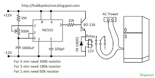
This is a simple freeze protector circuit diagram, also known as a timing circuit. It serves as a hobby project for beginners. This circuit can automatically operate any device after a fixed time once AC power supply is restored. The...
1-20 minutes a timing circuit
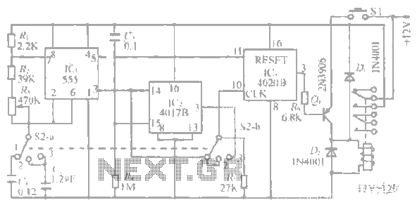
The system operates between 10 minutes to 2 hours, featuring a 100-line bell controlled by a multi-gear stick labeled S2 41f. The integrated circuit (IC) functions as a self-excited multivibrator. The device can manage binary pulses ranging from 3 to...
Automatic plant waterer
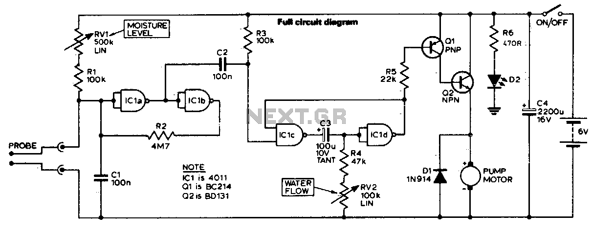
The unit consists of a sensor, timer, and electric water pump. The sensor is embedded in the soil, and when dry, the electronics operate the water pump for a preset time. The circuit is composed of a level-sensitive Schmitt trigger,...
Sensor-Activated Relay Pulser Circuit
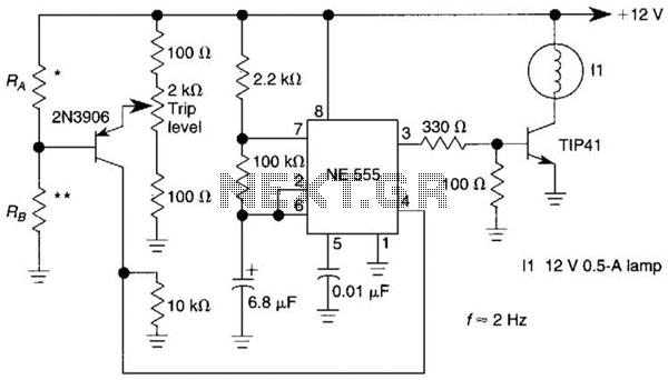
A sensor activates transistor Q1 to turn on the low-frequency 555 oscillator, which generates pulses to control LAMP II. The sensor may respond to variations in light or temperature. Either resistor RA or RB can function as the sensor, depending...
dyi setup and debugging guide
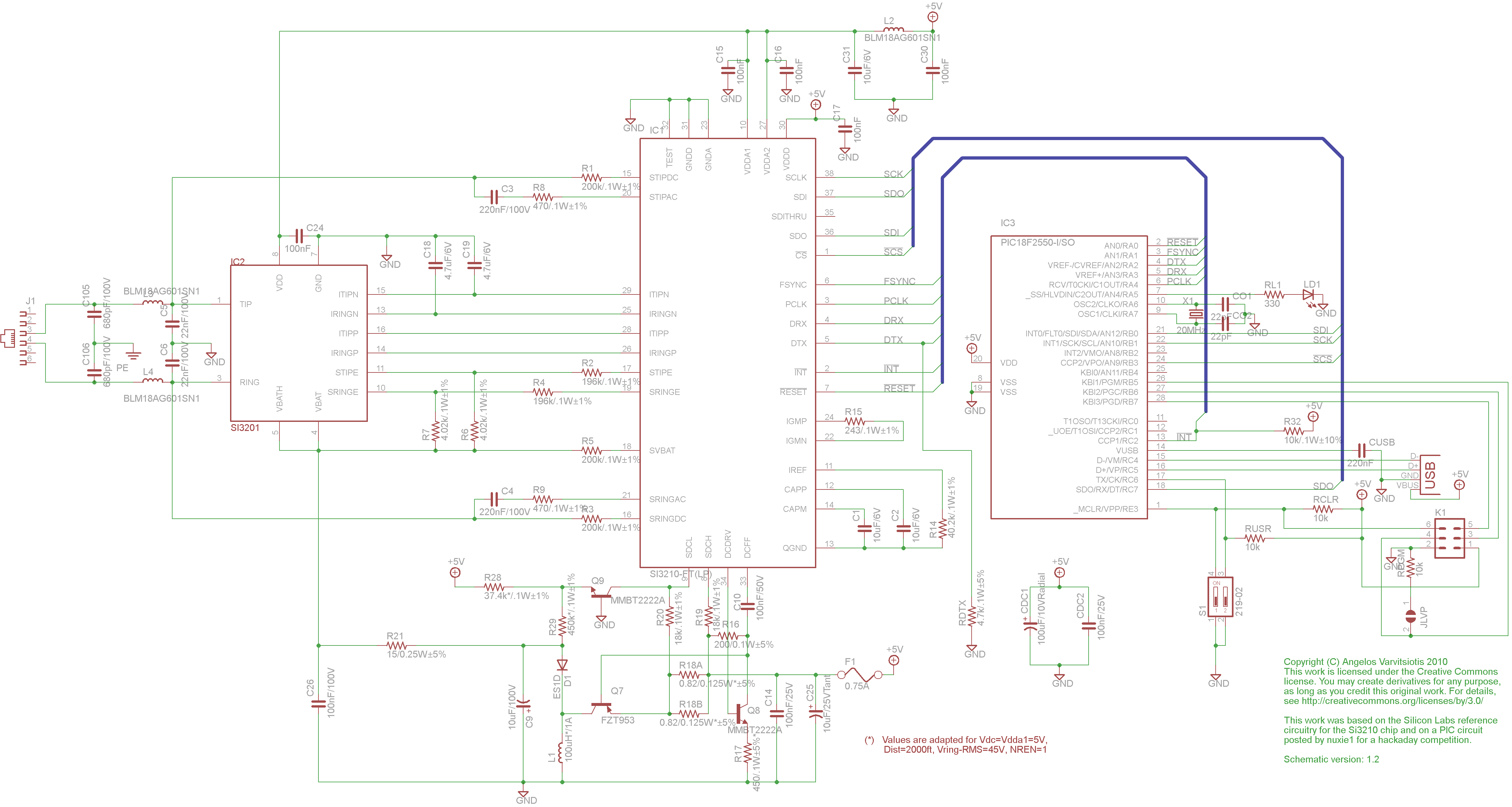
This page discusses the differences between assembled Open USB FXS dongle boards and DIY boards. While the assembled boards are fully tested and quality control approved, DIY boards may encounter various issues during assembly. Fortunately, most of these issues can...
Help with a schematic please
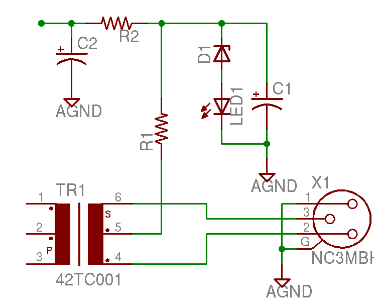
A project is underway to construct the CountryHick DI as illustrated on DIYFactory, incorporating a few minor modifications. The final design aims to be a 1U unit with four inputs.
The CountryHick DI (Direct Injection) box is a crucial tool in...
1-20 minutes a timing circuit
The system operates between 10 minutes to 2 hours, featuring a 100-line bell controlled by a multi-gear stick labeled S2 41f. The integrated circuit (IC) functions as a self-excited multivibrator. The device can manage binary pulses ranging from 3 to...
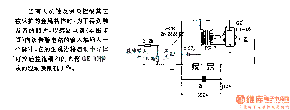
The alarm circuit diagram for safety box and other metal objects
When an individual touches the safety box or other protected metal objects, the sensor circuit generates a pulse to the alarm circuit. The positive edge of this pulse activates the semiconductor and thyristor flash GE, subsequently triggering the camera to...