


ICL7135 Typical Diagram and Datasheet
#ICL7135
#A/D converter
#CMOS
#BCD output
#digit drivers
#analog to digital
#measurement
#instrumentation
#schematic
#datasheet
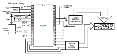
Description: The ICL7135 typical application schematic diagram is illustrated in the following circuit. This Analog to Digital (A/D) converter incorporates all necessary active devices on a single CMOS integrated circuit, featuring multiplexed BCD output and digit drivers.
The ICL7135 is a highly integrated A/D converter designed for precision measurement applications. It converts analog signals into a digital representation, facilitating the processing and display of data in various electronic systems. The device operates on a single supply voltage, typically ranging from 5V to 15V, which simplifies power management in circuit designs.
The schematic typically includes the following key components:
1. **Input Signal Conditioning**: This section may consist of operational amplifiers configured as buffers or amplifiers to condition the analog input signal, ensuring it is within the acceptable range for the A/D conversion process.
2. **Reference Voltage Source**: A stable reference voltage is crucial for accurate A/D conversion. The ICL7135 can utilize an external reference voltage source or an internal reference, depending on the application requirements.
3. **Multiplexed BCD Output**: The ICL7135 features a Binary-Coded Decimal (BCD) output, which allows for easy interfacing with digital displays or further processing units. The multiplexing capability reduces the number of output lines needed, streamlining the design.
4. **Digit Drivers**: These components are essential for driving the display elements, such as seven-segment displays. The digit drivers control the on/off states of individual segments based on the BCD output from the A/D converter.
5. **Control Logic**: The control logic manages the operation of the A/D converter, including the timing of conversions and the selection of input channels if multiple inputs are present.
6. **Decoupling Capacitors**: These are placed close to the power supply pins of the ICL7135 to filter out noise and ensure stable operation.
The ICL7135 is suitable for applications in digital voltmeters, sensor interfaces, and other systems requiring precise analog-to-digital conversion. Its compact design and integration of essential components make it an efficient choice for engineers looking to implement A/D conversion in their electronic designs.ICL7135 Typical Application Schematic Diagram appears in the following circuit illustration. This A/D (Analog to Digital) converter with all necessary active devices are contained on a single CMOS IC such multiplexed BCD output and digit drivers
The ICL7135 is a highly integrated A/D converter designed for precision measurement applications. It converts analog signals into a digital representation, facilitating the processing and display of data in various electronic systems. The device operates on a single supply voltage, typically ranging from 5V to 15V, which simplifies power management in circuit designs.
The schematic typically includes the following key components:
1. **Input Signal Conditioning**: This section may consist of operational amplifiers configured as buffers or amplifiers to condition the analog input signal, ensuring it is within the acceptable range for the A/D conversion process.
2. **Reference Voltage Source**: A stable reference voltage is crucial for accurate A/D conversion. The ICL7135 can utilize an external reference voltage source or an internal reference, depending on the application requirements.
3. **Multiplexed BCD Output**: The ICL7135 features a Binary-Coded Decimal (BCD) output, which allows for easy interfacing with digital displays or further processing units. The multiplexing capability reduces the number of output lines needed, streamlining the design.
4. **Digit Drivers**: These components are essential for driving the display elements, such as seven-segment displays. The digit drivers control the on/off states of individual segments based on the BCD output from the A/D converter.
5. **Control Logic**: The control logic manages the operation of the A/D converter, including the timing of conversions and the selection of input channels if multiple inputs are present.
6. **Decoupling Capacitors**: These are placed close to the power supply pins of the ICL7135 to filter out noise and ensure stable operation.
The ICL7135 is suitable for applications in digital voltmeters, sensor interfaces, and other systems requiring precise analog-to-digital conversion. Its compact design and integration of essential components make it an efficient choice for engineers looking to implement A/D conversion in their electronic designs.ICL7135 Typical Application Schematic Diagram appears in the following circuit illustration. This A/D (Analog to Digital) converter with all necessary active devices are contained on a single CMOS IC such multiplexed BCD output and digit drivers
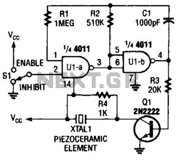
Cmos Piezo Driver Circuit
A CMOS gate and transistor buffer can be used as an effective driver for a piezoelectric transducer.
The use of a CMOS gate combined with a transistor buffer offers a robust solution for driving piezoelectric transducers. CMOS technology, known for its...
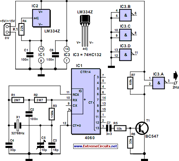
Thrifty 2Hz Clock
CMOS circuits are recognized for their low current consumption, which is particularly crucial for battery-powered applications. However, oscillators typically demand a significant amount of current. This proposed oscillator circuit achieves a very low current consumption of approximately 3 µA. It...
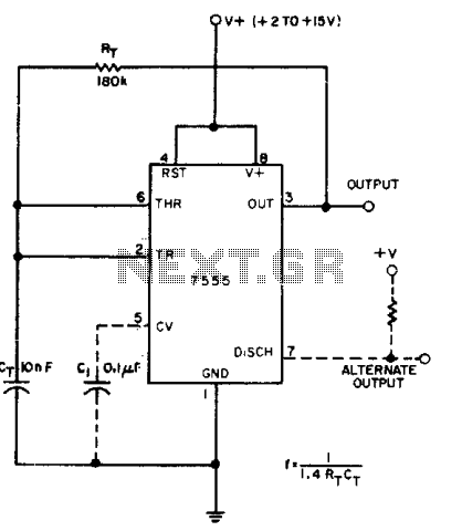
Cmos 555 astable generates square waves
A CMOS timer generates true square waves because, unlike the bipolar 555, its output swings from rail to rail. The component values shown give a frequency of about 400 Hz.
The CMOS timer circuit operates by utilizing complementary metal-oxide-semiconductor technology to...
High Speed A/D converter 12-bit
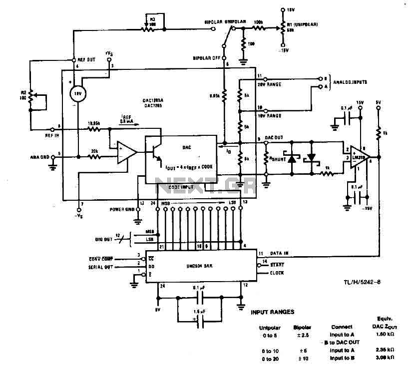
This system performs a complete conversion of 12 bits in both unipolar and bipolar modes. The converter is accurate to ±12-bit LSB with a typical gain temperature coefficient of 10 ppm/°C. In unipolar mode, the system operates within a range...
RealView 2.0
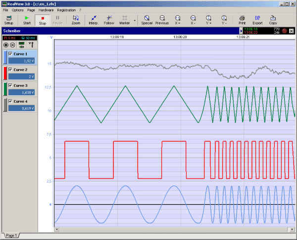
RealView is a measurement application, which records and plots measured values from analogue hardware devices in real-time. Several curves can be plotted into a single diagram. Several diagrams can be arranged on one or more pages if necessary. Plot options...
ELECTRONIC SCHEMATIC CIRCUIT DIAGRAMS
Electronic Schematic Circuit Diagrams Manual PDF Download.
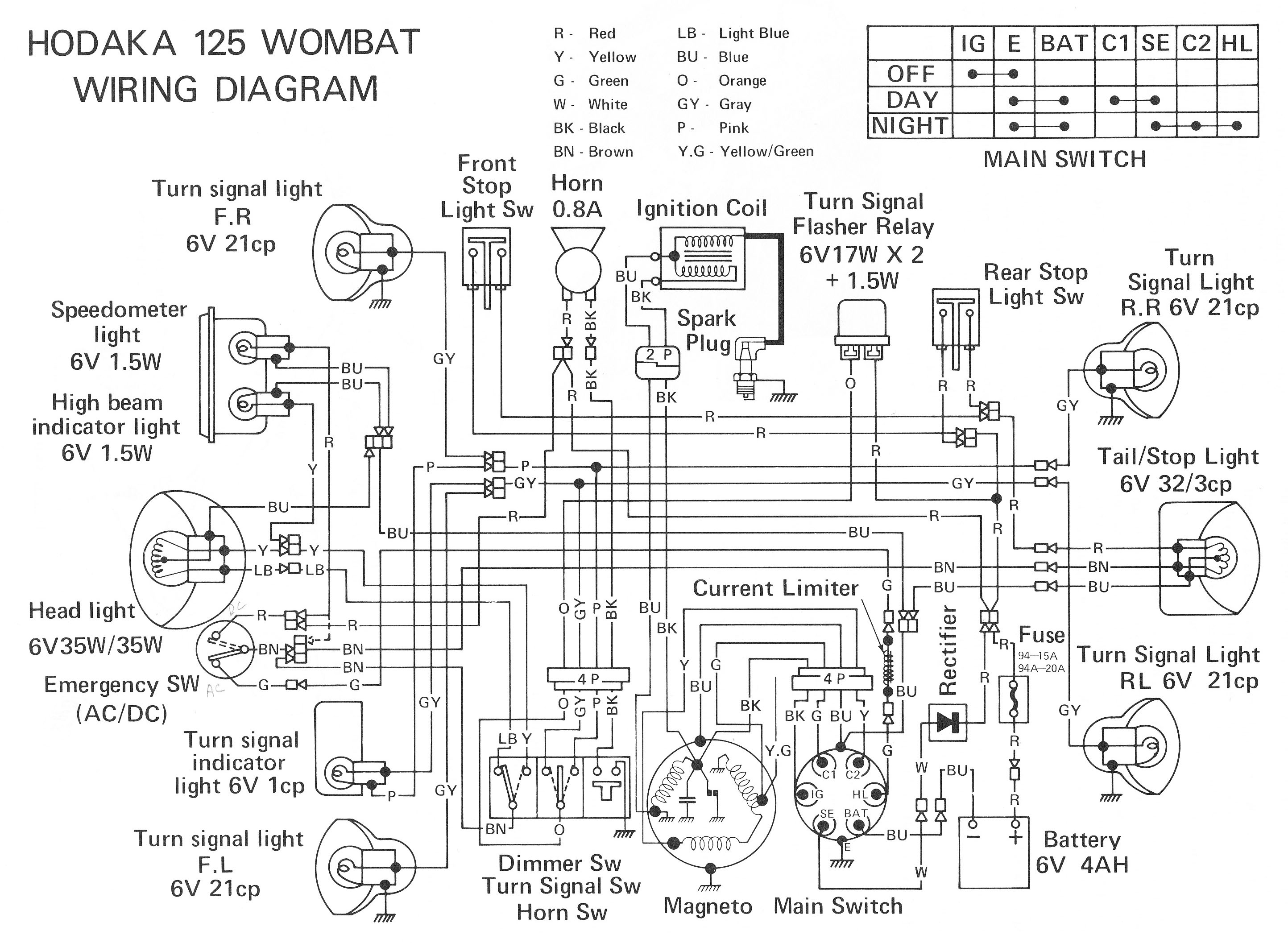
The document provides a comprehensive manual that focuses on electronic schematic circuit diagrams. These diagrams are essential tools for understanding and designing electronic circuits, offering visual representations of circuit components and their interconnections. The...
Blanket internal measurement circuit disconnection
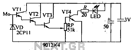
The internal disconnection circuit for a blanket operates on the principle of induction. It includes a wire approximately 2 cm in length that senses the proximity of a charged mains power source. When the sensing wire is close to the...
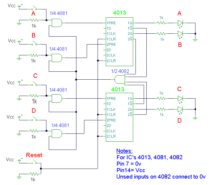
Quiz Circuit
This design utilizes four integrated circuits (ICs) and features four input circuits with four independent outputs, along with a single master reset switch. The outputs are configured with light-emitting diodes (LEDs), which can be modified to control lamps or buzzers....
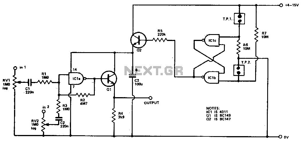
Cmos mixer
Four inputs can be mixed by duplicating the circuit to the left of C3 and using the fourth gate of ICI. Two gates are used in a touch-operated switching circuit that controls the voltage on the base of switching transistor...