


Inductance Bridge
#inductance
#bridge circuit
#measurement
#test frequency
#tuning capacitor
#AM
#electronics testing
#instrumentation
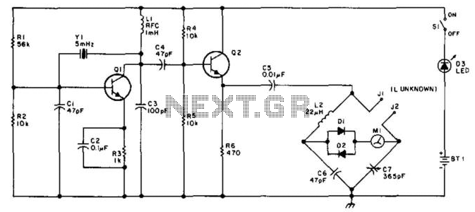
Description: This bridge will measure inductances from approximately 1 to 30 at a test frequency of 5 mHz. A 365-pF AM-type tuning capacitor is utilized as a variable element. The circuit should be assembled within a metal enclosure. Calibration can be performed using known inductors or by plotting a curve of the capacitance of the 365-pF capacitor against rotation and calculating the inductance from this. The measurement range can be adjusted by employing a different frequency crystal and/or varying L2 and C6.
The described inductance measurement bridge operates within a specified frequency range, making it suitable for low-frequency applications. The primary component, a 365-pF AM-type tuning capacitor, serves as a variable capacitor, allowing for fine adjustments in capacitance that are critical for accurate inductance measurements. The bridge configuration typically involves a combination of resistors, capacitors, and inductors arranged to create a balanced circuit, where the unknown inductance can be determined by comparing it against known values.
The metal enclosure is essential for shielding the circuit from electromagnetic interference, which could affect measurement accuracy. Proper grounding and layout practices should be observed to minimize noise and ensure stable operation.
Calibration is a vital step in ensuring measurement accuracy. This can be achieved by using known inductors to establish reference points or by creating a calibration curve that relates the capacitance of the variable capacitor to its rotation angle. This method allows for a more versatile approach to measurement, as it can accommodate variations in component tolerances and environmental factors.
The ability to modify the measurement range by changing the frequency crystal or adjusting components L2 and C6 adds to the flexibility of the bridge. This adaptability is particularly advantageous when measuring inductances across different ranges or in varying application scenarios. The choice of frequency can significantly impact the sensitivity and resolution of the measurements, thus careful selection based on the specific use case is recommended. This bridge will measure inductances from about 1 to 30 at a test frequency of 5 mHz. A 365-pF AM-type tuning capacitor is used as a variable element. The circuit should be constructed in a metal enclosure. Calibration can be done on known inductors or by plotting a curve of the capacitance of the 365-pF capacitor versus rotation and calculating the inductance from this. The range of measurement can be charged by using a different frequency crystal and/or variation of L2 and C6.
The described inductance measurement bridge operates within a specified frequency range, making it suitable for low-frequency applications. The primary component, a 365-pF AM-type tuning capacitor, serves as a variable capacitor, allowing for fine adjustments in capacitance that are critical for accurate inductance measurements. The bridge configuration typically involves a combination of resistors, capacitors, and inductors arranged to create a balanced circuit, where the unknown inductance can be determined by comparing it against known values.
The metal enclosure is essential for shielding the circuit from electromagnetic interference, which could affect measurement accuracy. Proper grounding and layout practices should be observed to minimize noise and ensure stable operation.
Calibration is a vital step in ensuring measurement accuracy. This can be achieved by using known inductors to establish reference points or by creating a calibration curve that relates the capacitance of the variable capacitor to its rotation angle. This method allows for a more versatile approach to measurement, as it can accommodate variations in component tolerances and environmental factors.
The ability to modify the measurement range by changing the frequency crystal or adjusting components L2 and C6 adds to the flexibility of the bridge. This adaptability is particularly advantageous when measuring inductances across different ranges or in varying application scenarios. The choice of frequency can significantly impact the sensitivity and resolution of the measurements, thus careful selection based on the specific use case is recommended. This bridge will measure inductances from about 1 to 30 at a test frequency of 5 mHz. A 365-pF AM-type tuning capacitor is used as a variable element. The circuit should be constructed in a metal enclosure. Calibration can be done on known inductors or by plotting a curve of the capacitance of the 365-pF capacitor versus rotation and calculating the inductance from this. The range of measurement can be charged by using a different frequency crystal and/or variation of L2 and C6.
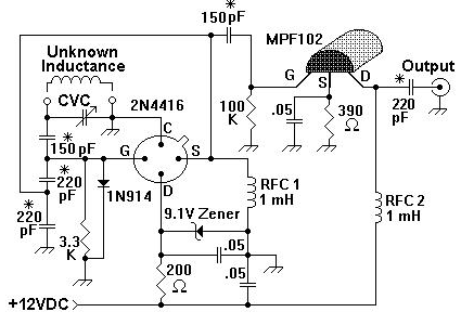
inductance meter
A device for measuring inductance. Over the years, articles describing devices for measuring inductance have appeared in QST and elsewhere, but none of them were suitable, so a new device has been developed.
The inductance measurement device is designed to provide...
measuring inductance
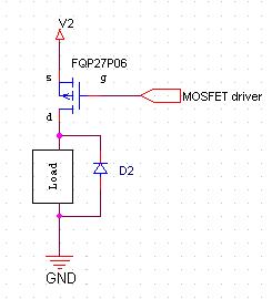
Choose the circuit that best suits your needs, although the one utilizing the LM339 is preferable. Both capacitors are 1 µF metallized film, but any non-polarized capacitor will suffice, provided it is close to 2 µF. Avoid using a capacitor...
Sense Small Inductance Changes Over A Wide Range
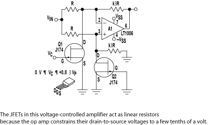
Small inductance changes on the order of 0.01% can easily be sensed over a wide range with a simple circuit connected to a serial port. Using a classic Colpitts oscillator interfaced to an eight-pin Atmel ATtiny12-8 microprocessor, the period of...
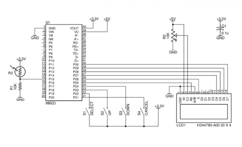
Advances in Measurement & Sensor Tech
This issue features articles on various measurement and sensor-related embedded design projects. Readers are encouraged to attempt similar projects and share their results. Starting on page 14, Petre Tzvetanov Petrov describes a multilevel audible logical probe design. Petrov notes that...
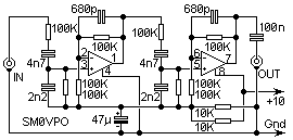
AM IF filter
Typical QRP receivers include Direct Conversion (DC) and simple Superheterodyne types. These receivers often have quite a wide AF bandwidth which can make intelligibility somewhat restricted, especially under difficult QRM conditions. Many commercial amateur transceivers also suffer from this, e.g.,...
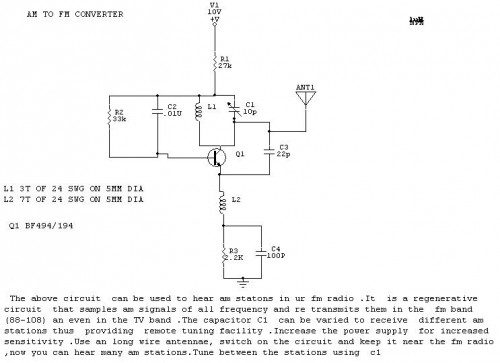
AM To FM converter
The objective is to enhance information transmission by utilizing articles. Please contact us via email at [email protected] within 15 days if there are any issues related to article content, copyright, or other concerns. The articles will be removed promptly.
To facilitate...
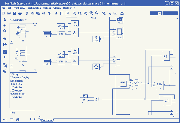
ProfiLab-Expert 4.0
The ProfiLab-Expert software allows you to develop your own digital or analogue measuring technology projects. It doesn't matter if you want to create analogue measurements or digital controls - you can realize it all. And for all this you don't...
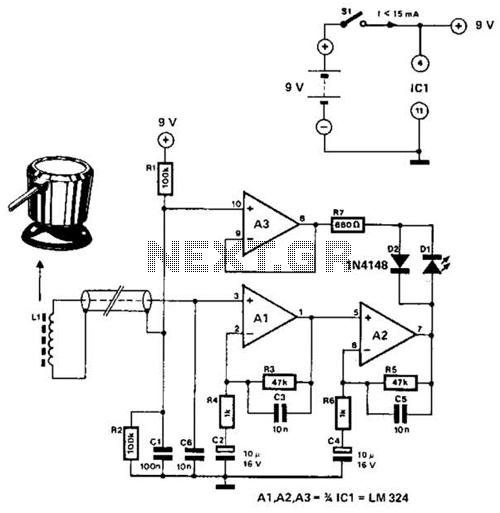
Linear Inductance Meter Circuit
The circuit utilizes the principle that in an RL circuit, the pulse width across the inductor is proportional to the inductance. This circuit indirectly measures the inductance using a digital voltmeter (DVM). The measurement range is approximately 5 to 250...
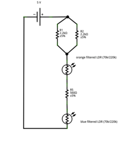
Instrumentation circuit
The mechanical chassis prototype, as illustrated in the accompanying image, was constructed using two materials: foam and aluminum. Foam was selected for its ease of manipulation, while aluminum was chosen for its excellent strength-to-weight ratio. The prototype features a rotary...