


Inductivity Meter Using IC 555
#IC 555
#inductance meter
#transistor
#resistor
#capacitor
#low cost
#electronics
#DIY
#testing
#circuit design
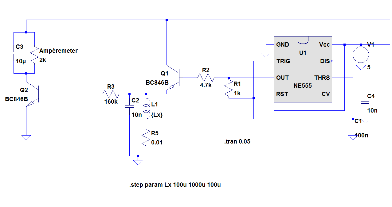
Description: The objective of the project is to construct a simple, low-cost inductance meter. The primary components of the project include an IC 555, a transistor, a resistor, and a capacitor.
The inductance meter designed in this project utilizes the IC 555 timer in astable mode to generate a square wave signal. The frequency of this square wave is influenced by the inductance of the coil being measured, as well as the associated resistor and capacitor values in the circuit.
The basic configuration involves connecting the inductor in series with a known resistor and capacitor. The output frequency from the IC 555 is monitored, typically using a frequency counter or a microcontroller, which can translate the frequency into an inductance value based on the known values of the resistor and capacitor.
A transistor is employed in this circuit to amplify the output signal from the IC 555, ensuring that the frequency can be accurately measured even at low inductance values. The choice of transistor should be appropriate for the frequency range and the expected output load.
Resistors are used to set the timing characteristics of the IC 555, while capacitors are critical for determining the oscillation frequency. The design must ensure that the capacitor used has a suitable tolerance and temperature coefficient to maintain accuracy in measurements.
Overall, this inductance meter project serves as a practical application of basic electronics principles, demonstrating the use of common components to create a functional measuring device. The simplicity and low cost make it accessible for educational purposes and hobbyist experimentation.The aim of the project is to build simple low cost inductance meter. The main parts of the project are IC 555, Transistor, resistor and capacitor..
The inductance meter designed in this project utilizes the IC 555 timer in astable mode to generate a square wave signal. The frequency of this square wave is influenced by the inductance of the coil being measured, as well as the associated resistor and capacitor values in the circuit.
The basic configuration involves connecting the inductor in series with a known resistor and capacitor. The output frequency from the IC 555 is monitored, typically using a frequency counter or a microcontroller, which can translate the frequency into an inductance value based on the known values of the resistor and capacitor.
A transistor is employed in this circuit to amplify the output signal from the IC 555, ensuring that the frequency can be accurately measured even at low inductance values. The choice of transistor should be appropriate for the frequency range and the expected output load.
Resistors are used to set the timing characteristics of the IC 555, while capacitors are critical for determining the oscillation frequency. The design must ensure that the capacitor used has a suitable tolerance and temperature coefficient to maintain accuracy in measurements.
Overall, this inductance meter project serves as a practical application of basic electronics principles, demonstrating the use of common components to create a functional measuring device. The simplicity and low cost make it accessible for educational purposes and hobbyist experimentation.The aim of the project is to build simple low cost inductance meter. The main parts of the project are IC 555, Transistor, resistor and capacitor..
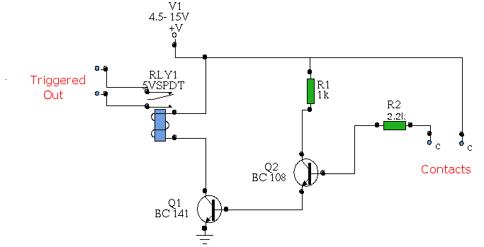
Water Activated Relay
In this circuit, two transistors are configured as a high-gain compound pair. Transistor T1 is likely a 2N2222A, while T2 is identified as a BC108. The current gain is calculated as the product of the beta values of each transistor,...
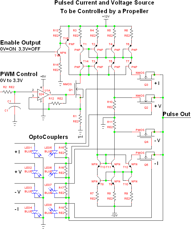
Full on transistor/fet curve tracer
The project involves adapting a curve tracer schematic, likely based on Metzger's circuit from the early 1970s, to integrate an ADC capture system and output the data to a 320x256 ELD panel. Additionally, a serial output will be included to...
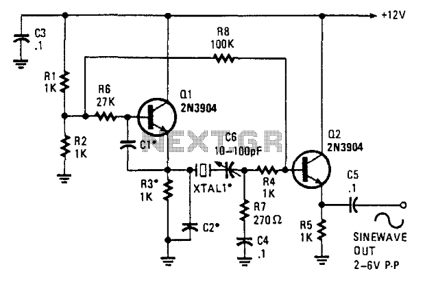
Two-Transistor Sine-Wave Oscillator
This oscillator employs two transistors and operates the crystal in its fundamental mode. Capacitors CT and C2 should be approximately 2,700 pF for 1 MHz, 680 pF for 5 MHz, and 330 pF for 10 MHz. A capacitance of 150...
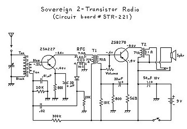
Two Transistor (Boys Radio) Schematic and Theory of Operation
An analysis of certain radios reveals the impressive engineering by Japanese designers, particularly in creating a radio capable of driving a speaker with only two transistors. The first transistor (Q1) serves a dual function; it operates as an RF amplifier...
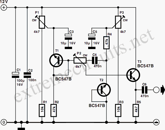
Symmetric Noise Source
When a transistor junction operates in Zener breakdown as a noise source, the resulting noise signal exhibits asymmetry in amplitude. This issue can be addressed by employing two transistors as independent noise sources. One transistor is connected with a series...
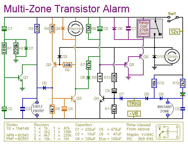
Multi-Zone Transistor-Based Intruder Alarm
This is a simple transistor-based burglar alarm circuit. Its features include automatic exit and entry delays, along with a timed bell cut-off and reset. It is designed to be used with standard types of normally-closed input devices such as magnetic...
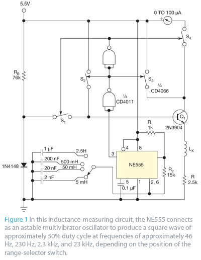
Use a transistor and an ammeter to measure inductance
Bipolar junction transistors transfer a current from a lower-resistance emitter to a higher-resistance collector. This property can be utilized to measure inductance.
Bipolar junction transistors (BJTs) are semiconductor devices that play a crucial role in electronic circuits by enabling the control...
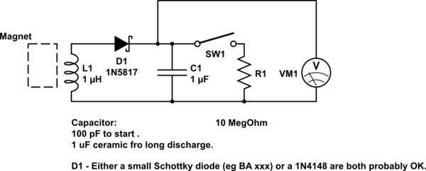
DIY kinetic energy harvester
A DIY kinetic energy harvester utilizing the electromagnetic method to generate electricity. The materials that will be used are currently known.
The project involves creating a kinetic energy harvester that converts mechanical energy from motion into electrical energy through electromagnetic induction....
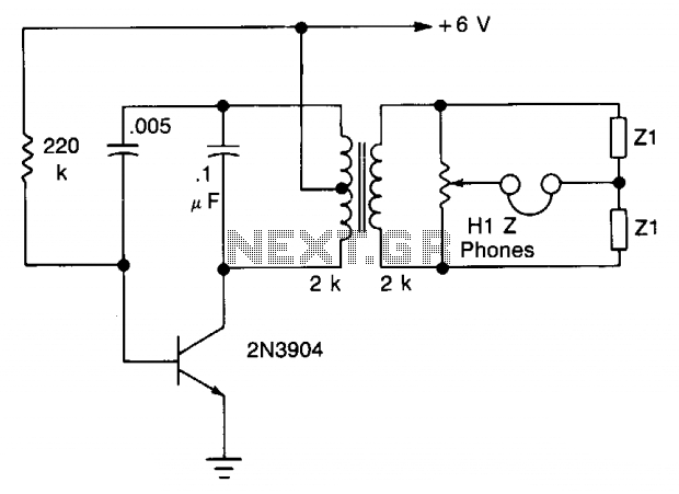
Bridge circuit
The transistor is configured as an audio oscillator, utilizing an audio transformer in the collector. The secondary winding is connected to a linear potentiometer. The ratio between the two sections of the potentiometer from the slider is proportional to the...