


Linear AC voltmeter circuit diagram
#AC voltmeter
#diode rectifiers
#electronic amplifiers
#linear scale
#power supply
#voltage measurement
#instrumentation
#circuit design
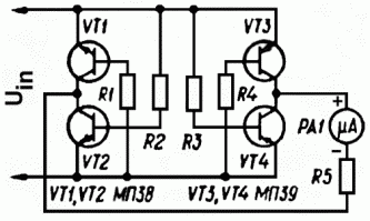
Description: The use of diode rectifiers in AC voltmeters with a low lower limit of measurement range (0.5-1 V) leads to significant nonlinearity of the scale due to the nonlinearity of the current-voltage characteristics of diodes. The incorporation of electronic amplifiers in rectifier circuits allows for scale linearization but requires a power supply. Simultaneously, a linear-bridge rectifier is known, with its arms formed by the collector-emitter junctions of four transistors, which receive bias voltage from the signal source. The operation of this rectifier is elaborated in detail, and a circuit diagram of an AC voltmeter based on this design is provided. The input voltage is applied directly to the emitters of transistors VT1-VT4 (one diagonal of the bridge), and the current proportional to this input voltage is measured by a microammeter connected across the collectors of transistors VT1-VT4 (the other diagonal of the bridge). Testing of this voltmeter indicated that the absolute value of the losses in the rectifier at input voltages above 0.1 V is almost independent of the voltage level, being approximately 40 mV for a load resistance of 10 kilohms (upper measurement limit of 1 V) and 60 mV for a load of 5 kilohms (upper measurement limit of 0.5 V). The components used for this testing were the same as those described, with resistors R1-R4 valued at 10 kΩ and a microammeter with full-scale deflection of 100 µA. The scale of the voltmeter was linear in the voltage ranges of 0.1-0.5 V and 0.1-1 V. The voltmeter was tested with an input sinusoidal signal at frequencies ranging from 10 to 10,000 Hz. The transfer characteristics (the relationship between the microammeter readings PA1 and the input voltage) for the upper measurement limits of 0.6 V and 1 V are illustrated. The characteristics of an ideal voltmeter, the described voltmeter, and a voltmeter based on a diode bridge with germanium diodes are compared. Any germanium transistors with a static current gain hFE of at least 50 can be utilized in this device. The microammeter PA1 can be any model with a full-scale deflection of 50-100 mA. The upper limit of measurement is determined by selecting the resistor R5. A voltmeter that does not require a power supply can be employed to measure AC voltage or current in circuits that are not galvanically isolated from the power supply unit. However, this voltmeter exhibits slightly increased current consumption from the measured circuit due to the shunting effect of the basic circuits of transistors VT1-VT4 and presents relative complexity in creating a multirange voltmeter.
The described AC voltmeter employs a linear-bridge rectifier configuration, which effectively mitigates the nonlinearity issues typically associated with traditional diode rectifiers. In this design, the four transistors operate in a bridge configuration, allowing for precise measurement of the input AC voltage. The transistors are biased by the input signal, ensuring that their operation remains within the linear region of their characteristics.
The microammeter serves as the output device, providing a direct reading of the current that is proportional to the input voltage. The careful selection of resistors R1-R4, all set to 10 kΩ, plays a critical role in establishing the desired sensitivity and linearity of the measurement. The testing conditions, including the application of a sinusoidal signal across a frequency range, further validate the performance of the voltmeter across various operating conditions.
The voltage drop across the rectifier components is a crucial parameter that has been quantified during testing. With a load resistance of 10 kΩ, the voltage loss remains consistent, indicating that the rectifier maintains its efficiency across the specified input voltage range. The ability to measure AC voltages without requiring an external power supply is particularly advantageous, facilitating usage in scenarios where isolation from power sources is necessary.
Overall, the described AC voltmeter represents an effective solution for low-voltage AC measurements, balancing the challenges of nonlinearity and power supply requirements while maintaining a straightforward operational framework. The design considerations and testing results underscore its utility in practical applications, providing a reliable tool for engineers and technicians in various fields.The use of diode rectifiers in AC voltmeters with a low lower limit of measurement range (0. 5. 1 V) leads to significant nonlinearity of the scale because of the nonlinearity of current-voltage characteristics of diodes. The use of electronic amplifiers in rectifier circuits allowing to linearize the scale but requires a power supply.
At the same t ime a linear-bridge rectifier [1, 2] is known, its shoulders are formed by junctions of the collector-emitter of the four transistors, this four transistors is getting the bias voltage from the signal source. The operation of this rectifier is described in detail in [2], a circuit diagram of an AC voltmeter on this basis is shown in Fig.
1. The input (measured) voltage is applied directly to the emitters of the transistors VT1-VT4 (the one of the diagonals of the bridge formed by them), the proportional to this input voltage current is measured by microammeter, connected across collectors of the transistors VT1-VT4 (the other diagonal of the bridge). Testing of this voltmeter showed that the absolute value of the losses in the rectifier at input voltage above 0.
1 V is almost independent of its level and is approximately 40 mV for a load resistance of 10 kilohms (the upper limit of measurement is 1 V) and 60 mV for a load of 5 kilohms (the upper limit of measurement is 0. 5 V). The components for this testing was used the same as described in fig. 1, value of resistors R1-R4 is 10k, microammeter with full-scale deflection of 100 uA. In other words, the scale of the voltmeter was linear in the voltage range of 0. 1. 0. 5V and 0. 1. 1V. The voltmeter was tested with an input sinusoidal signal with a frequency of 10. 10000 Hz. The transfer characteristics (the dependence of the microammeter readings PA1 of the input voltage) for the upper limits of measurement of 0.
6V and 1V are shown in Fig. 2a and 2b. Here is 1 - the characteristics of an ideal voltmeter, 2 - the described voltmeter, 3 - a voltmeter based on a diode bridge with germanium diodes D2B made in USSR. Any germanium transistors with a static current gain hFE not less than 50 can be used in this device.
Microammeter PA1 - any one with a full scale deflection of 50. 100 mA. The upper limit of the measurement is set by selection of the resistor R5. A voltmeter that does not require a power supply can be used, for example, to measure AC voltage or a current in a circuit that are not galvanically isolated with power supply unit. The disadvantage of this voltmeter - a slightly increased current consumption from the measured circuit (due to the shunting effect of the basic circuits of transistors VT1-VT4), and the relative complexity of creating a multirange voltmeter.
The described AC voltmeter employs a linear-bridge rectifier configuration, which effectively mitigates the nonlinearity issues typically associated with traditional diode rectifiers. In this design, the four transistors operate in a bridge configuration, allowing for precise measurement of the input AC voltage. The transistors are biased by the input signal, ensuring that their operation remains within the linear region of their characteristics.
The microammeter serves as the output device, providing a direct reading of the current that is proportional to the input voltage. The careful selection of resistors R1-R4, all set to 10 kΩ, plays a critical role in establishing the desired sensitivity and linearity of the measurement. The testing conditions, including the application of a sinusoidal signal across a frequency range, further validate the performance of the voltmeter across various operating conditions.
The voltage drop across the rectifier components is a crucial parameter that has been quantified during testing. With a load resistance of 10 kΩ, the voltage loss remains consistent, indicating that the rectifier maintains its efficiency across the specified input voltage range. The ability to measure AC voltages without requiring an external power supply is particularly advantageous, facilitating usage in scenarios where isolation from power sources is necessary.
Overall, the described AC voltmeter represents an effective solution for low-voltage AC measurements, balancing the challenges of nonlinearity and power supply requirements while maintaining a straightforward operational framework. The design considerations and testing results underscore its utility in practical applications, providing a reliable tool for engineers and technicians in various fields.The use of diode rectifiers in AC voltmeters with a low lower limit of measurement range (0. 5. 1 V) leads to significant nonlinearity of the scale because of the nonlinearity of current-voltage characteristics of diodes. The use of electronic amplifiers in rectifier circuits allowing to linearize the scale but requires a power supply.
At the same t ime a linear-bridge rectifier [1, 2] is known, its shoulders are formed by junctions of the collector-emitter of the four transistors, this four transistors is getting the bias voltage from the signal source. The operation of this rectifier is described in detail in [2], a circuit diagram of an AC voltmeter on this basis is shown in Fig.
1. The input (measured) voltage is applied directly to the emitters of the transistors VT1-VT4 (the one of the diagonals of the bridge formed by them), the proportional to this input voltage current is measured by microammeter, connected across collectors of the transistors VT1-VT4 (the other diagonal of the bridge). Testing of this voltmeter showed that the absolute value of the losses in the rectifier at input voltage above 0.
1 V is almost independent of its level and is approximately 40 mV for a load resistance of 10 kilohms (the upper limit of measurement is 1 V) and 60 mV for a load of 5 kilohms (the upper limit of measurement is 0. 5 V). The components for this testing was used the same as described in fig. 1, value of resistors R1-R4 is 10k, microammeter with full-scale deflection of 100 uA. In other words, the scale of the voltmeter was linear in the voltage range of 0. 1. 0. 5V and 0. 1. 1V. The voltmeter was tested with an input sinusoidal signal with a frequency of 10. 10000 Hz. The transfer characteristics (the dependence of the microammeter readings PA1 of the input voltage) for the upper limits of measurement of 0.
6V and 1V are shown in Fig. 2a and 2b. Here is 1 - the characteristics of an ideal voltmeter, 2 - the described voltmeter, 3 - a voltmeter based on a diode bridge with germanium diodes D2B made in USSR. Any germanium transistors with a static current gain hFE not less than 50 can be used in this device.
Microammeter PA1 - any one with a full scale deflection of 50. 100 mA. The upper limit of the measurement is set by selection of the resistor R5. A voltmeter that does not require a power supply can be used, for example, to measure AC voltage or a current in a circuit that are not galvanically isolated with power supply unit. The disadvantage of this voltmeter - a slightly increased current consumption from the measured circuit (due to the shunting effect of the basic circuits of transistors VT1-VT4), and the relative complexity of creating a multirange voltmeter.
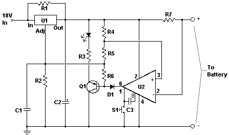
car battery charger circuit
The circuit is designed to be powered directly by a power supply, which is why it does not include a transformer, rectifier, or filter capacitors in the schematic. However, these components can be added if desired. To operate the circuit,...
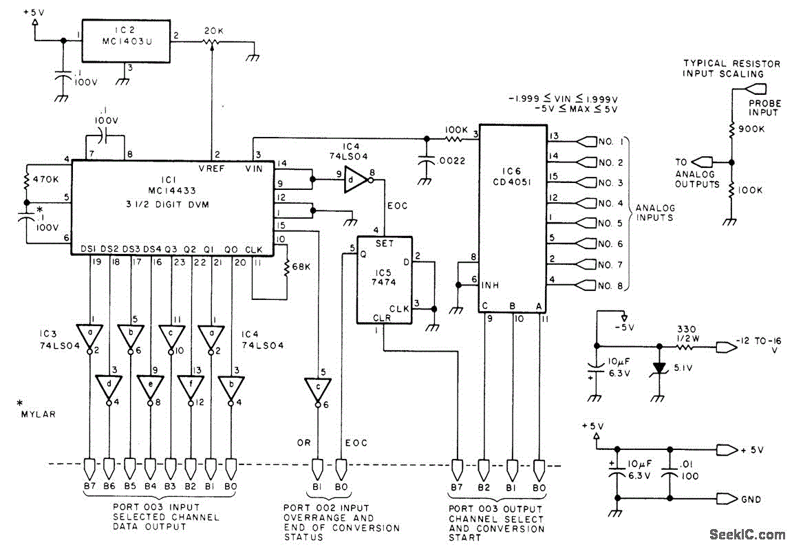
EIGHT CHANNEL COMPUTERIZED 3SUP1 SUP SUB2 SUB DIGIT_VM
Displays up to eight different DC voltages on a CRT terminal of a microprocessor under keyboard control, using BASIC commands and a BASIC routine provided in the article. Utilizes a modified Motorola MC14433 dual-lamp integrating analog-to-digital converter. An unknown voltage...
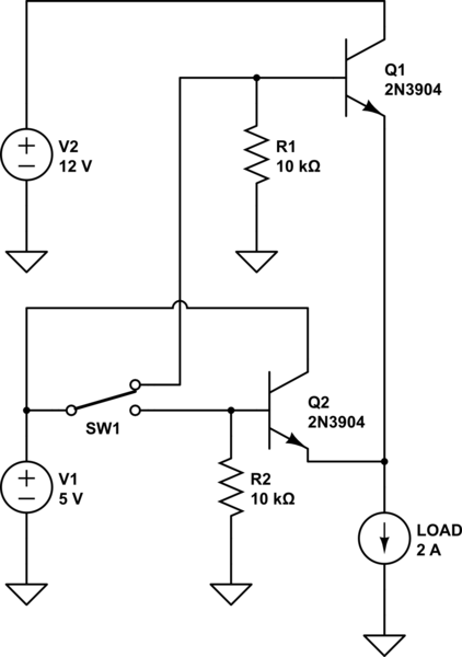
power How can I switch a high current with a low-rated switch
The project involves designing and constructing a breadboard power supply that draws power from an ATX-like switch-mode power supply (SMPS) using a 4-pin Molex connector. The design features a switch to select either a 12V or 5V output. However, the...

How to Boost Efficiency at Low Loads
Small additional circuitry during standby can significantly enhance efficiency. In a modern vehicle, multiple microcontrollers are required to support safety, navigation, entertainment, and comfort electronics.
The integration of additional circuitry during standby mode in automotive applications is crucial for optimizing power...
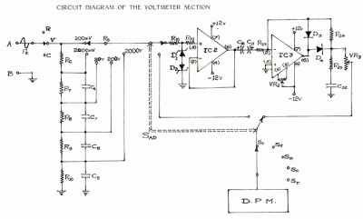
Test-Measurement 4
In circuit diagrams provided in equipment manuals, voltages at various points in the circuit are typically indicated. A deviation from these specified values suggests that a component has failed and can help in identifying faulty areas. Specifications include: D.C. Voltage...

symmetric 12v to 5v converter
Symmetric 12V to 5V converter power supply. Refer to the designated page for an explanation regarding the associated circuit diagram.
The symmetric 12V to 5V converter power supply is designed to efficiently step down a 12V input voltage to a regulated...
Remote tracking circuit schematics
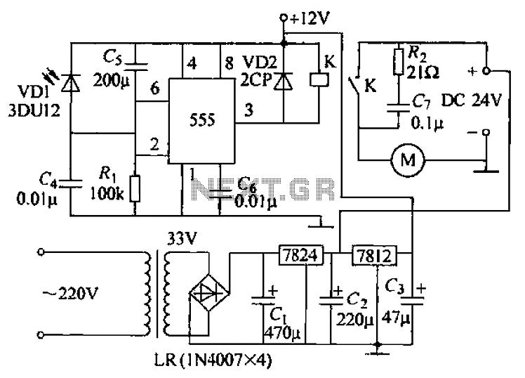
The circuit consists of two main components: (1) a power supply circuit featuring a transformer (T) that steps down AC 220V to 33V, followed by a full-wave rectifier, a filter, and a three-terminal regulator that outputs +24V. This circuit also...
A 12 Volt Switching Power Supply
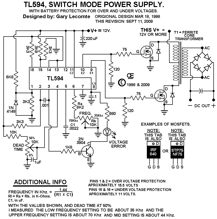
This circuit is designed for individuals needing to boost or drop a voltage. The output operates at high frequency but can be rectified and filtered to provide a DC output. When rectifying high frequencies, it is essential to utilize high-speed...
MDRC Mark 4 20 Amp Power Supply
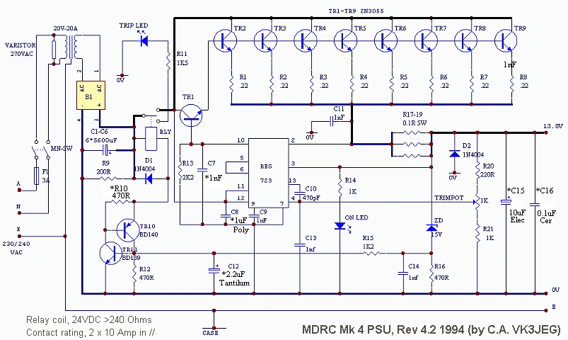
The MDRC committee approached the author to take on the role of Electronic Components and Project Officer, which was accepted without hesitation. Upon assuming the position, it became evident that more time would be required than initially anticipated, primarily for...