


LM3915 Vibration Meter
#LM3915
#vibration meter
#piezoelectric
#sensor
#measurement
#analog
#display
#circuit
#electronics
#monitoring
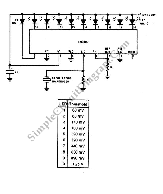
Description: A vibration meter circuit depicted in the schematic diagram utilizes the LM3915 as the primary active component. This vibration meter employs a piezoelectric sensor.
The vibration meter circuit is designed to measure and display vibration levels through a visual output. The core component, the LM3915, is a bar graph/LED dot display driver that can drive up to 10 LEDs in a linear or logarithmic scale. The circuit operates by converting the analog signal generated by the piezoelectric sensor into a corresponding visual representation of vibration intensity.
The piezoelectric sensor generates an electrical signal when subjected to mechanical stress or vibration. This signal is typically a small AC voltage that varies with the frequency and amplitude of the vibrations. To process this signal, the circuit includes an amplifier stage to boost the sensor output to a suitable level for the LM3915. This amplifier may consist of an operational amplifier configured in a non-inverting mode, ensuring that the output voltage is sufficient for accurate LED driving.
Following amplification, the signal may pass through a rectifier circuit to convert the AC signal from the piezoelectric sensor into a DC voltage. This rectified signal is then filtered to remove any high-frequency noise, ensuring that the LM3915 receives a clean and stable input voltage for accurate display.
The LM3915 is configured to operate in a dot mode, illuminating one LED at a time to indicate the level of vibration. The number of LEDs lit corresponds to the amplitude of the input signal, allowing users to quickly assess vibration levels visually. The circuit can be calibrated to represent specific vibration thresholds, enabling the user to set alarm levels or indicators based on the application requirements.
Power supply considerations for this circuit are crucial, as the LM3915 typically operates within a range of 3V to 25V. A regulated power supply ensures consistent performance and accurate readings. Additionally, protective components such as diodes may be included to safeguard the circuit from voltage spikes that could occur due to sudden vibrations.
Overall, this vibration meter circuit effectively combines the piezoelectric sensor's sensitivity with the visual output capabilities of the LM3915, making it a practical tool for monitoring vibration levels in various applications, including industrial machinery, automotive systems, and structural health monitoring.A vibration meter circuit shown in the following schematic diagram uses LM3915 a the main active component. This vibration meter uses a piezoelectric..
The vibration meter circuit is designed to measure and display vibration levels through a visual output. The core component, the LM3915, is a bar graph/LED dot display driver that can drive up to 10 LEDs in a linear or logarithmic scale. The circuit operates by converting the analog signal generated by the piezoelectric sensor into a corresponding visual representation of vibration intensity.
The piezoelectric sensor generates an electrical signal when subjected to mechanical stress or vibration. This signal is typically a small AC voltage that varies with the frequency and amplitude of the vibrations. To process this signal, the circuit includes an amplifier stage to boost the sensor output to a suitable level for the LM3915. This amplifier may consist of an operational amplifier configured in a non-inverting mode, ensuring that the output voltage is sufficient for accurate LED driving.
Following amplification, the signal may pass through a rectifier circuit to convert the AC signal from the piezoelectric sensor into a DC voltage. This rectified signal is then filtered to remove any high-frequency noise, ensuring that the LM3915 receives a clean and stable input voltage for accurate display.
The LM3915 is configured to operate in a dot mode, illuminating one LED at a time to indicate the level of vibration. The number of LEDs lit corresponds to the amplitude of the input signal, allowing users to quickly assess vibration levels visually. The circuit can be calibrated to represent specific vibration thresholds, enabling the user to set alarm levels or indicators based on the application requirements.
Power supply considerations for this circuit are crucial, as the LM3915 typically operates within a range of 3V to 25V. A regulated power supply ensures consistent performance and accurate readings. Additionally, protective components such as diodes may be included to safeguard the circuit from voltage spikes that could occur due to sudden vibrations.
Overall, this vibration meter circuit effectively combines the piezoelectric sensor's sensitivity with the visual output capabilities of the LM3915, making it a practical tool for monitoring vibration levels in various applications, including industrial machinery, automotive systems, and structural health monitoring.A vibration meter circuit shown in the following schematic diagram uses LM3915 a the main active component. This vibration meter uses a piezoelectric..

Sensor-Activated Relay Pulser Circuit
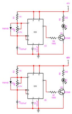
A sensor activates transistor Q1 to turn on the low-frequency 555 oscillator, which generates pulses to control LAMP II. The sensor may respond to variations in light or temperature. Either resistor RA or RB can function as the sensor, depending...
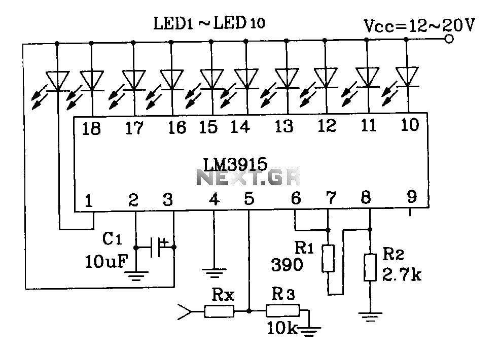
Constituting simple LM3915 audio power meter circuit
This document describes a simple LM3915 audio power meter circuit diagram. It notes that if the internal resistance of the speaker is 4 ohms, a resistor value of 10k ohms should be used for Rx. For an 8-ohm speaker, Rx...
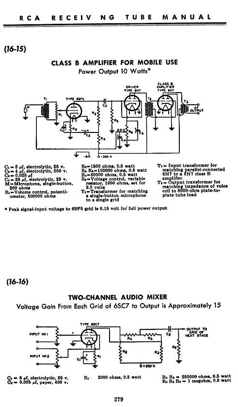
Analog Summing
A request to build an analog summing amplifier, preferably utilizing vacuum tubes to achieve the characteristic tube sound.
An analog summing amplifier is a circuit that combines multiple input signals into a single output signal. The use of vacuum tubes in...

Token number display
Introduction: Token Display Systems are ideal for banks, airports, public dealing offices, hospitals, doctors' clinics, restaurants, and other locations where people must wait in line. These systems allow customers to wait comfortably without standing in line; they only need to...

Audio Wattmeter Circuit with LM3915
This sound wattmeter utilizes a series of colored LEDs as a scale to display the relative power output of an amplifier in watts. It is designed for easy integration into a speaker box, requiring only a connection to a supply...
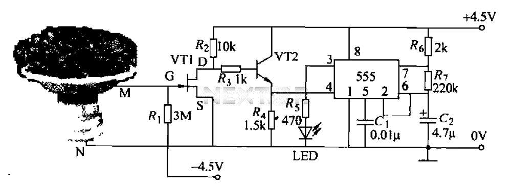
Pots water alarm circuit
The flowers in pots require watering, as relying solely on the observation of moist soil surfaces can be unreliable. To address this issue, a flower watering indicator has been developed. This circuit includes a field effect transistor (VT1), a second...
Automatic Room light Control With Bi Directional Visitor Counter
The objective of this project is to create a controller-based model that counts the number of individuals entering a specific room and activates the lighting accordingly. This is achieved through the use of sensors that detect the current number of...
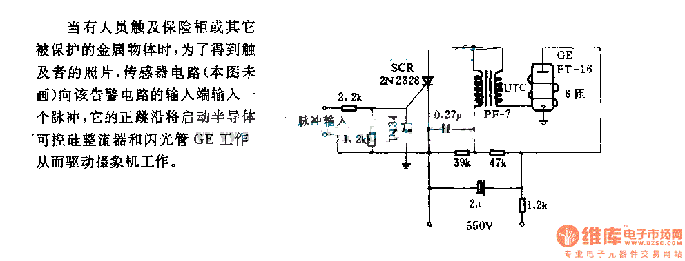
The alarm circuit diagram for safety box and other metal objects
When an individual touches the safety box or other protected metal objects, the sensor circuit generates a pulse to the alarm circuit. The positive edge of this pulse activates the semiconductor and thyristor flash GE, subsequently triggering the camera to...

Analog Voltage Camera-Image Tracker
By utilizing a low-cost RS-170 camera and this circuit, a voltage that indicates the position of an object within the camera's field of view is generated. IC2A and IC2B create a valid video gate that keeps IC3 in a reset...