


Logarithmic light-meter circuit
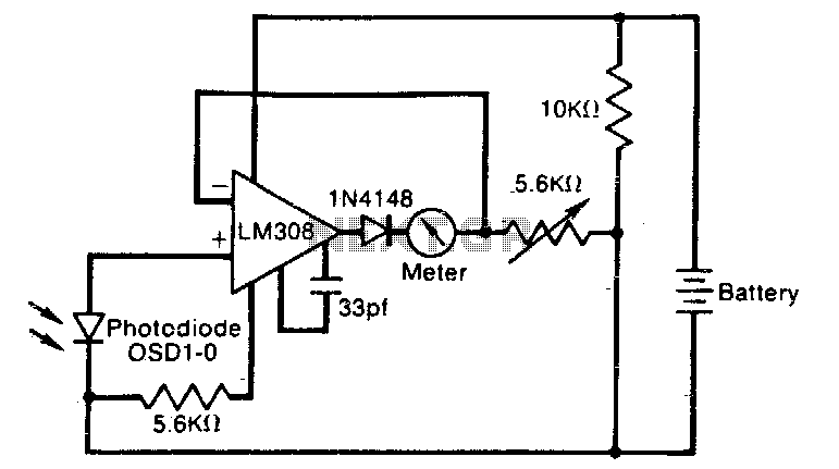
Description: The meter reading is directly proportional to the logarithm of the input light power. The logarithmic circuit behavior arises from the nonlinear diode p-n junction current/voltage relationship. The diode in the amplifier output prevents the output voltage from becoming negative, which may occur at low light levels due to amplifier bias currents. Resistor R1 adjusts the meter's full-scale deflection, enabling the meter to be calibrated.
The described circuit utilizes a logarithmic amplifier configuration to measure light intensity. The core principle relies on the logarithmic relationship between the input light power and the output voltage, which is facilitated by the characteristics of a p-n junction diode. This diode exhibits a nonlinear response to varying current, providing the necessary logarithmic scaling of the input signal.
In this configuration, the output of the amplifier is connected to a diode that ensures the output remains at or above zero volts. This is crucial in preventing the meter from saturating or "pegging" when the light levels are low, which could lead to misleading readings due to amplifier bias currents. The bias currents can cause the output to dip below zero, resulting in inaccurate meter deflections.
Resistor R1 plays a pivotal role in calibrating the meter. By adjusting the resistance value, the full-scale deflection of the meter can be modified, allowing for precise calibration according to the specific requirements of the application. This adjustment ensures that the meter accurately reflects the logarithmic relationship between the input light power and the meter reading, providing reliable and consistent measurements across a range of light intensities.
Overall, this circuit is an effective solution for applications requiring accurate light intensity measurements, leveraging the unique properties of diodes and amplifiers to achieve a logarithmic response.The meter reading is directlyjproportiona! to the logarithm of the input light power. The logarithmic circuit behavior arises from the nonlineardiode pnjunction current/voltage relationship The diode in the amplifier output prevents output voltage from becoming negative (thereby pegging the meter), which may happen at low lightlevels due to amplifier bias currents. Rl adjusts the meter full-scale deflection, enabling the meter to be calibrated.
The described circuit utilizes a logarithmic amplifier configuration to measure light intensity. The core principle relies on the logarithmic relationship between the input light power and the output voltage, which is facilitated by the characteristics of a p-n junction diode. This diode exhibits a nonlinear response to varying current, providing the necessary logarithmic scaling of the input signal.
In this configuration, the output of the amplifier is connected to a diode that ensures the output remains at or above zero volts. This is crucial in preventing the meter from saturating or "pegging" when the light levels are low, which could lead to misleading readings due to amplifier bias currents. The bias currents can cause the output to dip below zero, resulting in inaccurate meter deflections.
Resistor R1 plays a pivotal role in calibrating the meter. By adjusting the resistance value, the full-scale deflection of the meter can be modified, allowing for precise calibration according to the specific requirements of the application. This adjustment ensures that the meter accurately reflects the logarithmic relationship between the input light power and the meter reading, providing reliable and consistent measurements across a range of light intensities.
Overall, this circuit is an effective solution for applications requiring accurate light intensity measurements, leveraging the unique properties of diodes and amplifiers to achieve a logarithmic response.The meter reading is directlyjproportiona! to the logarithm of the input light power. The logarithmic circuit behavior arises from the nonlineardiode pnjunction current/voltage relationship The diode in the amplifier output prevents output voltage from becoming negative (thereby pegging the meter), which may happen at low lightlevels due to amplifier bias currents. Rl adjusts the meter full-scale deflection, enabling the meter to be calibrated.
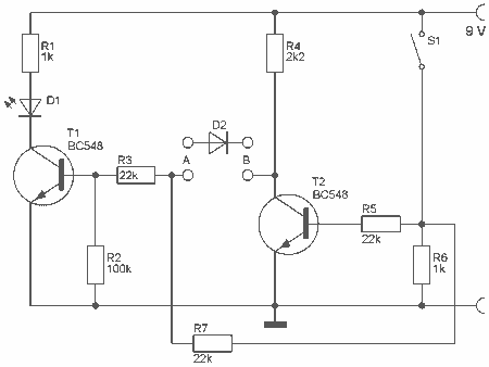
Diode Tester schematic
With this tester you can check whether a diode is working properly. In the table you can see what LED to indicate the positions of the switch and condition of the diode. The circuit can be connected to a 9...
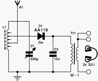
diode radio circuit
Currently, the most commonly available headphones have an impedance ranging from 2 to 32 ohms. This relatively low value renders them unsuitable for certain designs. However, with some clever modifications, these headphones can be effectively utilized in such applications. To...
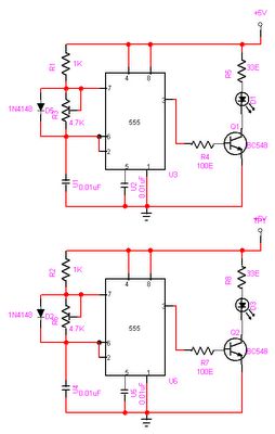
Automatic Room light Control With Bi Directional Visitor Counter
The objective of this project is to create a controller-based model that counts the number of individuals entering a specific room and activates the lighting accordingly. This is achieved through the use of sensors that detect the current number of...
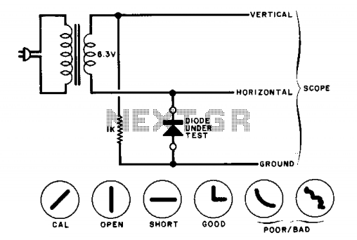
Diode tester
The circuit will display curves on an oscilloscope, depending on the state of the diode. To calibrate, replace the diode with a 1000-ohm resistor and adjust the oscilloscope gains for a 45-degree line. The drawings illustrate some expected results.
The described...
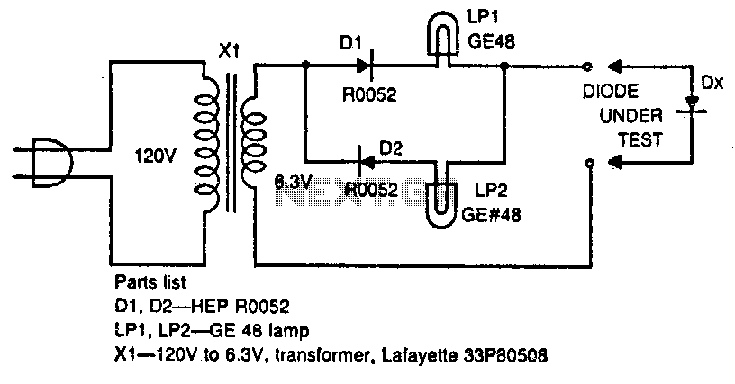
Diode tester
The circuit tests whether a diode is open, shorted, or functioning correctly. If lamp A lights, the diode under test is functional. When lamp B is lit, the diode is good but connected backwards. When both lamps are lit, the...
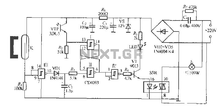
Gate automatic lamp circuit
The circuit utilizes multiple integrated circuits to form an automatic lighting device that is activated by door and window sensors. It includes CD4093 digital integrated circuits, a relay, and a power supply circuit. The system typically remains closed when a...
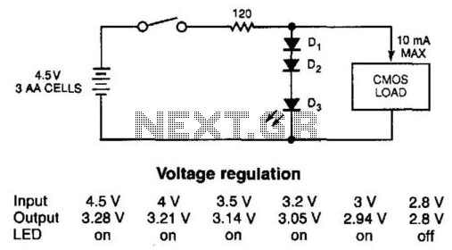
Diode Cmos Stabilizer
The simple diode network can stabilize the voltage supplied to CMOS circuitry from a battery. D1 and D2 must have a combined forward-voltage drop of about 1.5 V. D3 is an LED with a forward-voltage drop of about 1.7 V....
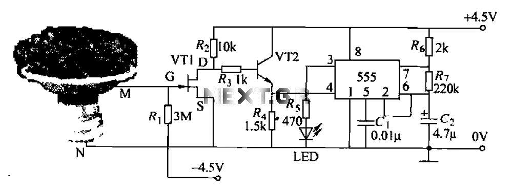
Pots water alarm circuit
The flowers in pots require watering, as relying solely on the observation of moist soil surfaces can be unreliable. To address this issue, a flower watering indicator has been developed. This circuit includes a field effect transistor (VT1), a second...
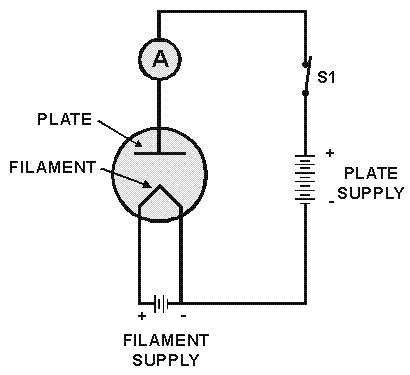
Diode Tube
The diode tube under examination is essentially Edison’s early incandescent bulb containing a plate. The term "diode" refers to the two elements or electrodes within the glass container that constitute the tube. Shortly after the discovery of the Edison effect,...