


Looking for schematic diagram of AD574 IC
#AD574
#ADC
#analog-to-digital converter
#12-bit
#successive approximation
#schematic
#measurement
#instrumentation
#electronics
#IC
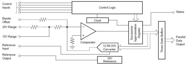
Description: The ADC574A is a 12-bit successive approximation analog-to-digital converter (ADC). The request is for information on how this integrated circuit (IC) operates.
The ADC574A operates by converting an analog input signal into a digital output signal using the successive approximation method. This technique involves several key steps and components within the IC.
1. **Input Signal Sampling**: The ADC begins by sampling the analog input voltage. This is typically done through a sample-and-hold circuit, which captures the input voltage and holds it steady during the conversion process.
2. **Successive Approximation Register (SAR)**: The core of the ADC574A is the successive approximation register. This digital circuit generates a binary number that approximates the input voltage. It does this by comparing the sampled voltage to the output of a digital-to-analog converter (DAC) that is controlled by the SAR.
3. **Comparison Process**: The SAR starts with the most significant bit (MSB) set to 1 and all other bits set to 0. The DAC converts this binary number back into an analog voltage. The output of the DAC is then compared to the input voltage. If the DAC output is less than the input voltage, the SAR retains the current bit; if it is greater, the SAR resets that bit to 0. This process continues for each bit, moving from the MSB to the least significant bit (LSB).
4. **Digital Output Generation**: Once all bits have been processed, the SAR outputs a complete binary representation of the analog input voltage. The result is a 12-bit digital number that corresponds to the input signal.
5. **Timing and Control**: The ADC574A requires a clock signal to synchronize the conversion process. The conversion time is determined by the clock frequency and the number of bits being converted.
6. **Reference Voltage**: The accuracy of the ADC conversion is influenced by the reference voltage applied to the circuit. A stable and precise reference voltage ensures that the digital output accurately represents the analog input.
7. **Output Format**: The digital output can be accessed in either binary or two's complement format, depending on the configuration of the ADC. This allows for flexibility in how the data is processed by subsequent digital systems.
The ADC574A is suitable for a wide range of applications, including industrial automation, data acquisition systems, and instrumentation, where precise analog-to-digital conversion is critical.hi, Dears . I want to use AD574 ( The ADC574A is a 12-BIT successive approximation analog-to-digital converter .) i want to know , How work this IC ?? ..
The ADC574A operates by converting an analog input signal into a digital output signal using the successive approximation method. This technique involves several key steps and components within the IC.
1. **Input Signal Sampling**: The ADC begins by sampling the analog input voltage. This is typically done through a sample-and-hold circuit, which captures the input voltage and holds it steady during the conversion process.
2. **Successive Approximation Register (SAR)**: The core of the ADC574A is the successive approximation register. This digital circuit generates a binary number that approximates the input voltage. It does this by comparing the sampled voltage to the output of a digital-to-analog converter (DAC) that is controlled by the SAR.
3. **Comparison Process**: The SAR starts with the most significant bit (MSB) set to 1 and all other bits set to 0. The DAC converts this binary number back into an analog voltage. The output of the DAC is then compared to the input voltage. If the DAC output is less than the input voltage, the SAR retains the current bit; if it is greater, the SAR resets that bit to 0. This process continues for each bit, moving from the MSB to the least significant bit (LSB).
4. **Digital Output Generation**: Once all bits have been processed, the SAR outputs a complete binary representation of the analog input voltage. The result is a 12-bit digital number that corresponds to the input signal.
5. **Timing and Control**: The ADC574A requires a clock signal to synchronize the conversion process. The conversion time is determined by the clock frequency and the number of bits being converted.
6. **Reference Voltage**: The accuracy of the ADC conversion is influenced by the reference voltage applied to the circuit. A stable and precise reference voltage ensures that the digital output accurately represents the analog input.
7. **Output Format**: The digital output can be accessed in either binary or two's complement format, depending on the configuration of the ADC. This allows for flexibility in how the data is processed by subsequent digital systems.
The ADC574A is suitable for a wide range of applications, including industrial automation, data acquisition systems, and instrumentation, where precise analog-to-digital conversion is critical.hi, Dears . I want to use AD574 ( The ADC574A is a 12-BIT successive approximation analog-to-digital converter .) i want to know , How work this IC ?? ..
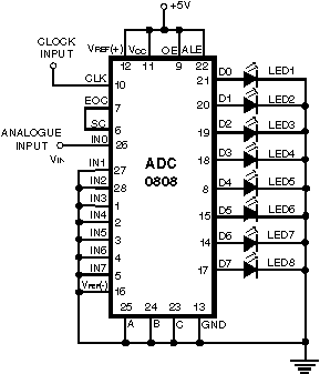
Simple Analog to Digital Converter (ADC)
Normally, an analog-to-digital converter (ADC) requires interfacing through a chip to convert analog signals into digital format. This necessitates both hardware and software, resulting in increased complexity and overall cost. The circuit presented here is configured around the ADC 0808,...
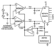
AD8225 High Resolution Analog/Digital Converter (ADC)Circuit and Datasheet
The Common Mode Rejection Ratio (CMRR) facilitates the rejection of high-frequency common-mode voltages, leading to the attenuation of elevated ambient noise levels from utility lines, industrial machinery, and other sources of radiation. The circuit diagram presented illustrates the advantages of...
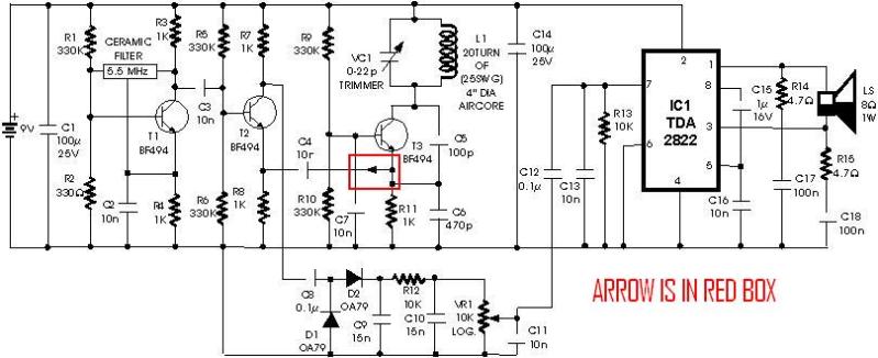
metal detector project circuit
A schematic diagram for a metal detector has been found. The project does not need to be original and can be sourced from the internet. There are several questions regarding this schematic. One query pertains to a small arrow connected...
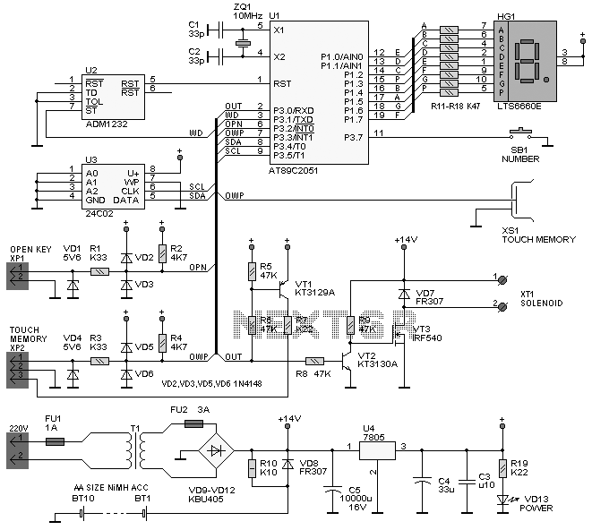
Analog to Digital Conversion
The project involves implementing analog-to-digital conversion using the ADC0804LCN 8-bit A/D converter. A circuit will be designed and programmed so that when an analog signal is input, the corresponding digital voltage is displayed on an LCD. Essentially, the circuit will...
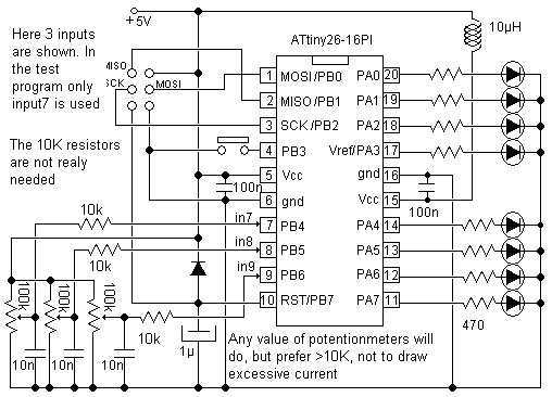
10 Bit analog to digital converter
Study the Analog to Digital capabilities of Atmel ATtiny26. This tiny but mighty IC is really a miracle. One special thing is the internal 10-inputs multiplexed ADC circuit which can convert analog voltages to bytes. This check circuit uses only...
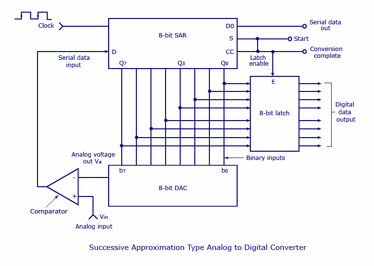
Analog to Digital Converters (AD)
This type of converter is used to convert analog voltage to its corresponding digital output. The function of the analog-to-digital converter is exactly opposite to that of a digital-to-analog converter. Like a digital-to-analog converter, an analog-to-digital converter is also specified...
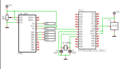
Analog To Digital Converter
An Analog-to-Digital Converter (ADC) is a circuit integrated into a single chip designed to convert analog signals into digital signals. Typically, an 8-bit ADC chip converts an analog signal ranging from 0 to 5 volts into a digital level ranging...
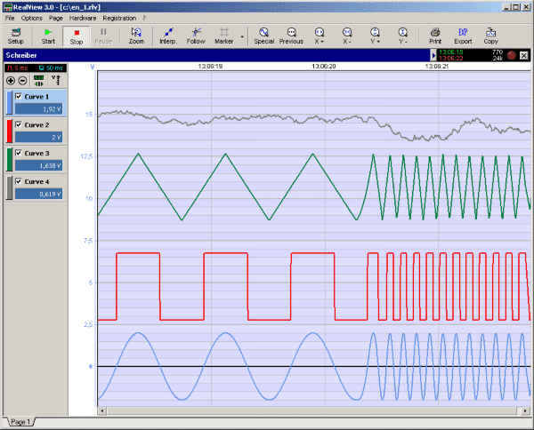
RealView 2.0
RealView is a measurement application, which records and plots measured values from analogue hardware devices in real-time. Several curves can be plotted into a single diagram. Several diagrams can be arranged on one or more pages if necessary. Plot options...
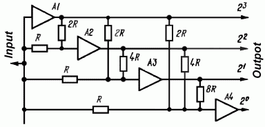
Simple Analog to Digital Converter
The simplest Analog to Digital Converter (ADC) can be constructed as shown in Figure 1. The input voltage, which can range from zero up to the power supply voltage (Vcc), is converted to a parallel binary code at the outputs...