


Measuring Impedance with Circuit Maker
#impedance measurement
#signal generator
#AC frequency analysis
#shunt resistor
#circuit analysis
#amplifiers
#filters
#oscillators
#current source
#frequency sweep
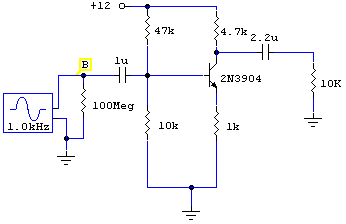
Description: To measure the input impedance of an unknown circuit, first set the signal generator to a current source with a magnitude of 1 amp. A shunt resistor of 100 megohms is also required. This setup is beneficial for measuring amplifiers, filters, and oscillator circuits. Perform an AC frequency analysis by setting the start limit to 1 Hz and the end limit according to your preference. For audio applications, 1 MHz may be suitable, although other limits can be chosen for filter circuits. With the input set to 1 amp, the y-axis will directly display the input impedance of the circuit. Cursor B can be moved across the spectrum to facilitate reading of intermediate points. The input impedance increases at low frequencies due to the 1 µF input capacitor, reaching infinite impedance at DC or 0 Hz. The 100 MΩ shunt resistor across the generator is essential because the output impedance of a current source in Circuit Maker is infinite; omitting this resistor will lead to a simulation error. A similar approach is utilized for measuring output impedance. The signal generator is again set to a 1 amp current source and connected to the output circuit terminals. In this scenario, a 10 kΩ load resistor is present, making a high-value parallel shunt resistance unnecessary. During the AC frequency analysis, the output voltage is recorded across the frequency range. According to Ohm's Law (V = I × R), with I set at 1 amp, the output waveform provides a direct measurement in ohms of the circuit's output impedance. This method is quick and serves as an alternative to measuring output voltage divided by circuit output current. Both input and output impedance measurements should be compatible with all versions of Circuit Maker.
To accurately measure the input impedance of an unknown circuit, the initial configuration involves utilizing a signal generator set as a current source, specifically adjusted to deliver 1 amp. The inclusion of a 100 megohm shunt resistor is critical; it serves to prevent simulation errors that arise due to the infinite output impedance characteristic of a current source in simulation software such as Circuit Maker. This configuration is particularly effective for analyzing amplifiers, filters, and oscillator circuits.
The process begins with an AC frequency analysis, where the frequency range is established by setting a start limit at 1 Hz, while the end limit can be adjusted based on the specific circuit requirements, with 1 MHz being a common choice for audio applications. By maintaining the input at 1 amp, the y-axis of the resultant graph will directly represent the input impedance of the circuit under test. The use of Cursor B allows for precise readings at various points across the frequency spectrum, enhancing the accuracy of the analysis.
As frequency decreases, the input impedance is observed to rise, primarily due to the influence of a 1 µF input capacitor, ultimately reaching an infinite impedance at DC or 0 Hz. This behavior is essential for understanding the frequency response of the circuit.
For output impedance measurements, the signal generator is similarly configured to 1 amp and connected to the output terminals of the circuit. Given the presence of a 10 kΩ load resistor, the necessity for a high-value parallel shunt resistance is negated. As the AC frequency analysis is conducted, the output voltage across the frequency spectrum is recorded, allowing for the application of Ohm's Law to derive the output impedance. Specifically, with a fixed current of 1 amp, the output waveform directly correlates to the circuit's output impedance in ohms.
This methodology provides a rapid and effective means of evaluating both input and output impedance, enhancing the understanding of circuit behavior across varying frequencies. Notably, the compatibility of these measurements with all versions of Circuit Maker ensures broad applicability in electronic circuit analysis.To measure the input impedance of an unknown circuit first set the signal genaerator to a current source of magnitude 1 amp. You also need a shunt resistor of 100 Meg. This setup is useful for measuring amplifiers, filter and oscillator circuits. Use the signal generator as below: Now perform an AC frequency analysis. Set the start limit to 1 Hz, set the end limit to your choice. Depending on your circuit, 1MHz may be OK for audio work, though you can set any start and end limits for filter circuits. As the input is now 1 amp, the y-axis now directly reads the input impedance of your circuit. Cursor B can be scrolled across the spectrum, see example below: The cursors allow easier reading intermediate points.
The input impedance increases at low frequencies due to the 1u input capacitor. The impedance would be infinite at DC or 0Hz. The 100M shunt resistor across the generator is necessary as the output impedance of a current source in circuit maker is infinite, omitting this resistor will result in a simulation error. A similar method is used for measuring output impedance. The signal generator is again set to a current source of magnitude 1 amp. The generator will be applied to the output circuits terminals, as shown below. In this circuit, the output has a 10 k load resistor so a high value parallel shunt resistance is superfluous.
When an AC frequency analysis is performed, the graph reads the output voltage across the frequency range. From ohms law V = I x R. As I is set at 1 amp, then the output waveform is now a direct measurement in ohms of the circuits output impedance.
Results are shown below: This is a quick method and an alternative to measuring output voltage divided by circuit output current. Both input and output impedance measurements should be compatible with all versions of circuit maker.
To accurately measure the input impedance of an unknown circuit, the initial configuration involves utilizing a signal generator set as a current source, specifically adjusted to deliver 1 amp. The inclusion of a 100 megohm shunt resistor is critical; it serves to prevent simulation errors that arise due to the infinite output impedance characteristic of a current source in simulation software such as Circuit Maker. This configuration is particularly effective for analyzing amplifiers, filters, and oscillator circuits.
The process begins with an AC frequency analysis, where the frequency range is established by setting a start limit at 1 Hz, while the end limit can be adjusted based on the specific circuit requirements, with 1 MHz being a common choice for audio applications. By maintaining the input at 1 amp, the y-axis of the resultant graph will directly represent the input impedance of the circuit under test. The use of Cursor B allows for precise readings at various points across the frequency spectrum, enhancing the accuracy of the analysis.
As frequency decreases, the input impedance is observed to rise, primarily due to the influence of a 1 µF input capacitor, ultimately reaching an infinite impedance at DC or 0 Hz. This behavior is essential for understanding the frequency response of the circuit.
For output impedance measurements, the signal generator is similarly configured to 1 amp and connected to the output terminals of the circuit. Given the presence of a 10 kΩ load resistor, the necessity for a high-value parallel shunt resistance is negated. As the AC frequency analysis is conducted, the output voltage across the frequency spectrum is recorded, allowing for the application of Ohm's Law to derive the output impedance. Specifically, with a fixed current of 1 amp, the output waveform directly correlates to the circuit's output impedance in ohms.
This methodology provides a rapid and effective means of evaluating both input and output impedance, enhancing the understanding of circuit behavior across varying frequencies. Notably, the compatibility of these measurements with all versions of Circuit Maker ensures broad applicability in electronic circuit analysis.To measure the input impedance of an unknown circuit first set the signal genaerator to a current source of magnitude 1 amp. You also need a shunt resistor of 100 Meg. This setup is useful for measuring amplifiers, filter and oscillator circuits. Use the signal generator as below: Now perform an AC frequency analysis. Set the start limit to 1 Hz, set the end limit to your choice. Depending on your circuit, 1MHz may be OK for audio work, though you can set any start and end limits for filter circuits. As the input is now 1 amp, the y-axis now directly reads the input impedance of your circuit. Cursor B can be scrolled across the spectrum, see example below: The cursors allow easier reading intermediate points.
The input impedance increases at low frequencies due to the 1u input capacitor. The impedance would be infinite at DC or 0Hz. The 100M shunt resistor across the generator is necessary as the output impedance of a current source in circuit maker is infinite, omitting this resistor will result in a simulation error. A similar method is used for measuring output impedance. The signal generator is again set to a current source of magnitude 1 amp. The generator will be applied to the output circuits terminals, as shown below. In this circuit, the output has a 10 k load resistor so a high value parallel shunt resistance is superfluous.
When an AC frequency analysis is performed, the graph reads the output voltage across the frequency range. From ohms law V = I x R. As I is set at 1 amp, then the output waveform is now a direct measurement in ohms of the circuits output impedance.
Results are shown below: This is a quick method and an alternative to measuring output voltage divided by circuit output current. Both input and output impedance measurements should be compatible with all versions of circuit maker.
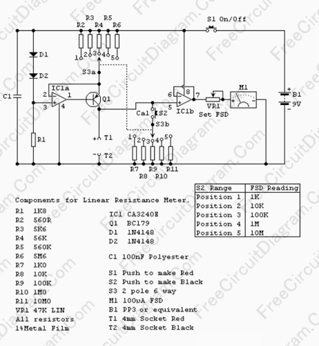
Using Current Source To Make Linear Scale Analog Ohm Meter
Many analog ohm meters have a non-linear scale, which results in poorer resolution at higher resistance values. This is due to the use of inexpensive current sources.
Many analog ohm meters operate on a principle where the scale is not linear,...
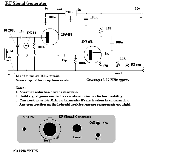
Signal Generators Circuits
Converting periodic waveforms to square waves is essential for extracting clock signals from data, creating waveform generators, and developing timing-pulse generators. A square-wave conversion circuit is more advantageous when the duty cycle of the square wave is variable and controllable....
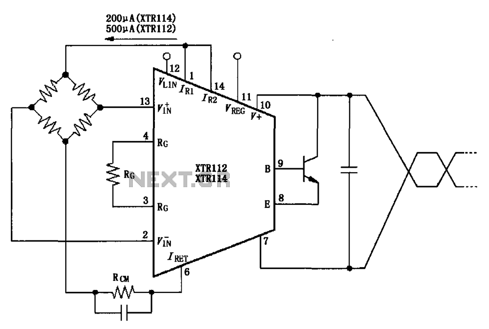
XTR112 114 bridge input current excitation circuit diagram
The two current sources within the chip (1 foot and 14 feet out) provide excitation. The output of each current source is 0.2 mA (XTR114) or 0.5 A (XTR112). The common mode input voltage is adjustable, ranging from 1.25 to...
Filters
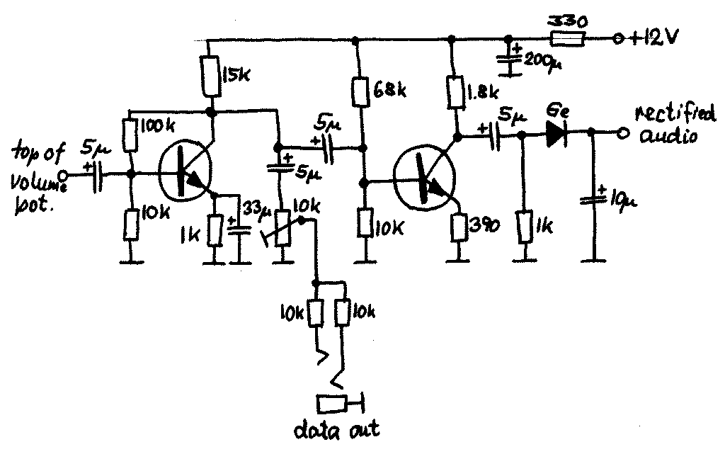
This option has the advantage that one does not need to change anything in the receiver itself. However, since any filter will give some attenuation of the signal, this will degrade the noise figure of the receiver and thus limit...

The Multi-purpose signal generator circuit
The multi-purpose signal generator circuit consists of integrated circuit oscillators and frequency dividers. It generates square waves ranging from high frequencies to sub-audio frequencies and also produces a frequency standard in the VHF range. The alternative oscillator section feeds the...
AudioWave 2.0
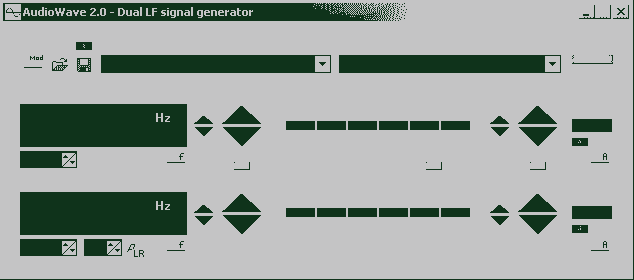
With AudioWave 2.0 your soundcard becomes a comfortable LF-signal-generator, which produces signals from 1Hz to 20 kHz with a resolution of 1 Hz. Phase shift between left and right channel is adjustable from 180° to +180° and an attenuator can...
Current Source
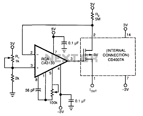
This circuit utilizes commonly available components to create a 0-to-200-nA current source. It incorporates a PMOS transistor from the input stage of a DC4007A, which is more accessible than a standalone PMOS transistor. The CA3130 operational amplifier functions as a...
Signal Generator 20KHz
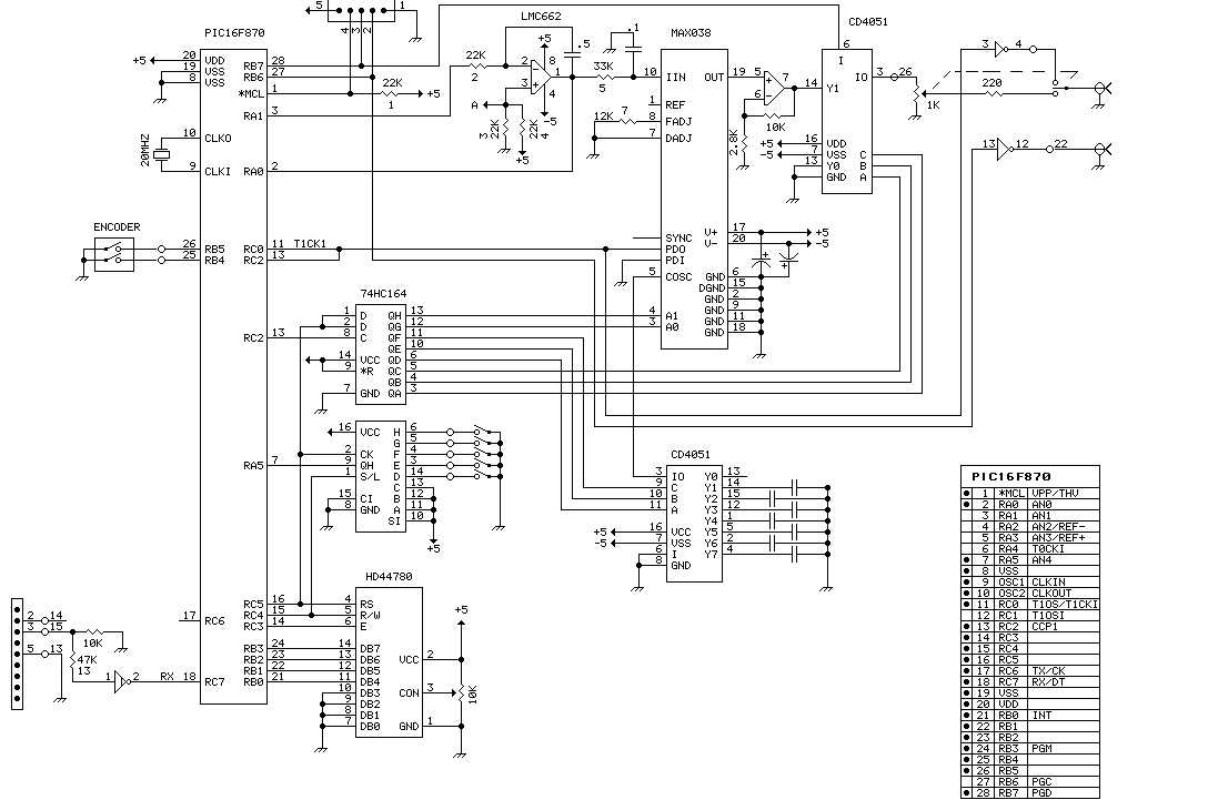
This function generator IC is specified to work to 20 MHz. So far, this unit works nicely to 50KHz. Since I seldom need signals higher than that, it has taken up a happy home on my workbench and further development...
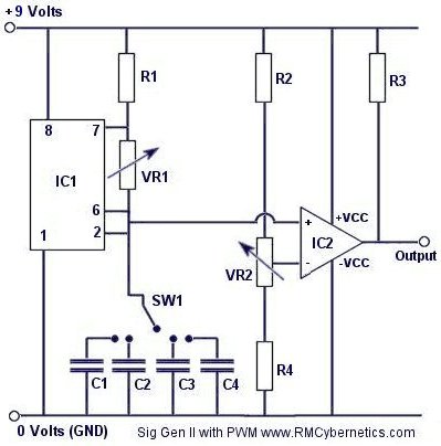
DIY Homemade Signal Generator with Pulse Width Modulation
Construct a signal generator using readily available components. It should produce a square wave with variable frequency and adjustable pulse width. This device can be utilized for various applications, including DC motor speed regulation, dimming of lamps or LEDs, transformer...