


PIC 16F88 Digital Thermometer Light Meter and resistance ohm meter
#PIC 16F88
#digital thermometer
#light meter
#resistance meter
#ADC
#LCD display
#WINTEK WD-C2401P
#microcontroller
#sensor interface
#measurement
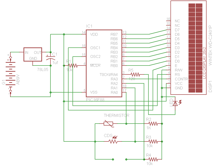
Description: The initial concept for this project involves interfacing the WINTEK WD-C2401P LCD panel with a PIC microcontroller. The intention is to incorporate several ADC readings to provide useful information on the LCD. PORTB on the PIC serves as the data port for the LCD, while the Enable, Register Select, and Reset pins are connected to PORTA. Once the LCD is initialized, the PIC reads ADC values from a thermistor, a CDS cell, and a resistor (if connected) through a voltage divider. This voltage divider converts variations in sensor resistance into corresponding voltage changes. The output voltage (Vout) is calculated using the formula Vout = Vdd * (R2 / (R2 + R1)), where R1 is the sensor's resistance. Any change in R1 results in a change in output voltage. The PIC, equipped with a 10-bit ADC resolution, has 1024 possible steps. If the microcontroller operates at 5V, each step corresponds to an increment of 5/1024 = 0.004882813V. The ADC value can be determined by dividing the input voltage by 0.004882813, allowing for precise calculations of sensor resistance. To convert this resistance into a human-readable format, calibration with real-world instruments is necessary to extrapolate the values. Additionally, since the display lacks a backlight, an LED is connected to PORTA4 to activate when ambient light falls below a specific threshold.
The circuit design involves several key components and connections to achieve the intended functionality. The WINTEK WD-C2401P LCD panel is interfaced with the PIC microcontroller, which is responsible for controlling the display and processing sensor data. The LCD requires proper initialization, which involves sending specific commands to set up the display parameters. The data lines connected to PORTB allow for the transmission of characters and commands to the LCD, while PORTA manages control signals such as Enable, Register Select, and Reset.
ADC readings are taken from the thermistor and CDS cell, which are connected through a voltage divider configuration. The voltage divider consists of two resistors, R1 (the sensor) and R2 (a fixed resistor), which together determine the output voltage based on the resistance of R1. This output voltage is fed into the ADC input of the PIC microcontroller, where it is digitized for further processing. The 10-bit ADC allows for a detailed resolution of the analog input, enabling accurate readings of the sensor outputs.
Calibration of the sensors is crucial for ensuring that the displayed values are meaningful and accurate. This involves comparing the ADC readings against known values obtained from calibrated instruments, allowing for the development of a calibration curve or formula that correlates ADC values to actual resistance measurements.
The inclusion of an LED connected to PORTA4 serves as a visual indicator of ambient light levels. When the light level drops below a predetermined threshold, the LED illuminates, providing a simple yet effective feedback mechanism for users.
Overall, this project combines display technology with sensor interfacing and analog-to-digital conversion to create a versatile system capable of presenting real-time environmental data on an LCD panel.My original idea for this project was simply to try and interface the WINTEK WD-C2401P lcd panel to the pic (see my previous post). I figured it would be fun to add a couple of ADC readings to display something useful on the lcd. PORTB on the PIC is used as the data port for the LCD. The Enable, Register Select and Reset are tied to PORTA. Once th e LCD is initialized, the PIC reads the ADC values from the thermistor, CDS cell and resistor (if connected) via a voltage divider. The voltage divider translates any change in resistance from the sensors into changes in voltage. The Vout is calculated as Vdd*(R2/R2+R1). ) So any change in R1 (the sensor`s resistance) will result in a change in the output voltage. In order to translate this into the ADC value, a 10 bit ADC resolution microcontroller will have 1024 (2 to the power of 10) possible steps.
So if the controller is operating on 5V then each step will increment the voltage by 5/1024 =0. 004882813V every increment. So the value in the ADC will be the voltage input at the ADC divided by 0. 004882813. This allows for an accurate calculation of the resistance of the sensor. In order to translate the resistance to useful human readable form, its necessary to calibrate the sensors using real life instruments and extrapolating the values to the resistance offered. Since the display does not have any backlight, an LED is connected to PORTA4 to turn on whenever the light falls below a certain threshold.
The circuit design involves several key components and connections to achieve the intended functionality. The WINTEK WD-C2401P LCD panel is interfaced with the PIC microcontroller, which is responsible for controlling the display and processing sensor data. The LCD requires proper initialization, which involves sending specific commands to set up the display parameters. The data lines connected to PORTB allow for the transmission of characters and commands to the LCD, while PORTA manages control signals such as Enable, Register Select, and Reset.
ADC readings are taken from the thermistor and CDS cell, which are connected through a voltage divider configuration. The voltage divider consists of two resistors, R1 (the sensor) and R2 (a fixed resistor), which together determine the output voltage based on the resistance of R1. This output voltage is fed into the ADC input of the PIC microcontroller, where it is digitized for further processing. The 10-bit ADC allows for a detailed resolution of the analog input, enabling accurate readings of the sensor outputs.
Calibration of the sensors is crucial for ensuring that the displayed values are meaningful and accurate. This involves comparing the ADC readings against known values obtained from calibrated instruments, allowing for the development of a calibration curve or formula that correlates ADC values to actual resistance measurements.
The inclusion of an LED connected to PORTA4 serves as a visual indicator of ambient light levels. When the light level drops below a predetermined threshold, the LED illuminates, providing a simple yet effective feedback mechanism for users.
Overall, this project combines display technology with sensor interfacing and analog-to-digital conversion to create a versatile system capable of presenting real-time environmental data on an LCD panel.My original idea for this project was simply to try and interface the WINTEK WD-C2401P lcd panel to the pic (see my previous post). I figured it would be fun to add a couple of ADC readings to display something useful on the lcd. PORTB on the PIC is used as the data port for the LCD. The Enable, Register Select and Reset are tied to PORTA. Once th e LCD is initialized, the PIC reads the ADC values from the thermistor, CDS cell and resistor (if connected) via a voltage divider. The voltage divider translates any change in resistance from the sensors into changes in voltage. The Vout is calculated as Vdd*(R2/R2+R1). ) So any change in R1 (the sensor`s resistance) will result in a change in the output voltage. In order to translate this into the ADC value, a 10 bit ADC resolution microcontroller will have 1024 (2 to the power of 10) possible steps.
So if the controller is operating on 5V then each step will increment the voltage by 5/1024 =0. 004882813V every increment. So the value in the ADC will be the voltage input at the ADC divided by 0. 004882813. This allows for an accurate calculation of the resistance of the sensor. In order to translate the resistance to useful human readable form, its necessary to calibrate the sensors using real life instruments and extrapolating the values to the resistance offered. Since the display does not have any backlight, an LED is connected to PORTA4 to turn on whenever the light falls below a certain threshold.
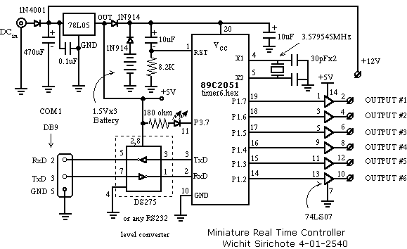
Miniature Real-time Controller
This is my long history the device that controls my home's night light, air-conditioner, etc. The device is a Miniature Real-time Controller. The circuit uses only three chips, a 89C2051, DS275 (or MAX232), and 74LS07 open collector driver. The scheduler...
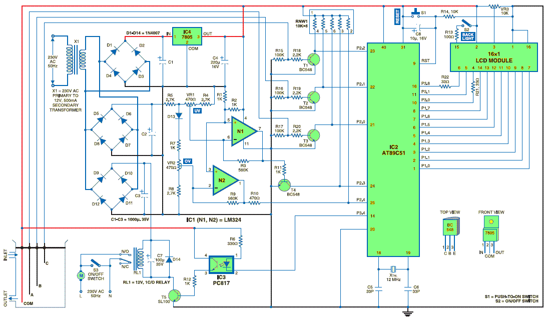
Water Level controller
The microcontroller-based water level controller and motor protector manages the on and off states of the motor based on the water level in the overhead tank (OHT). It regulates the tank's water level through a microcontroller, thereby providing automatic protection...
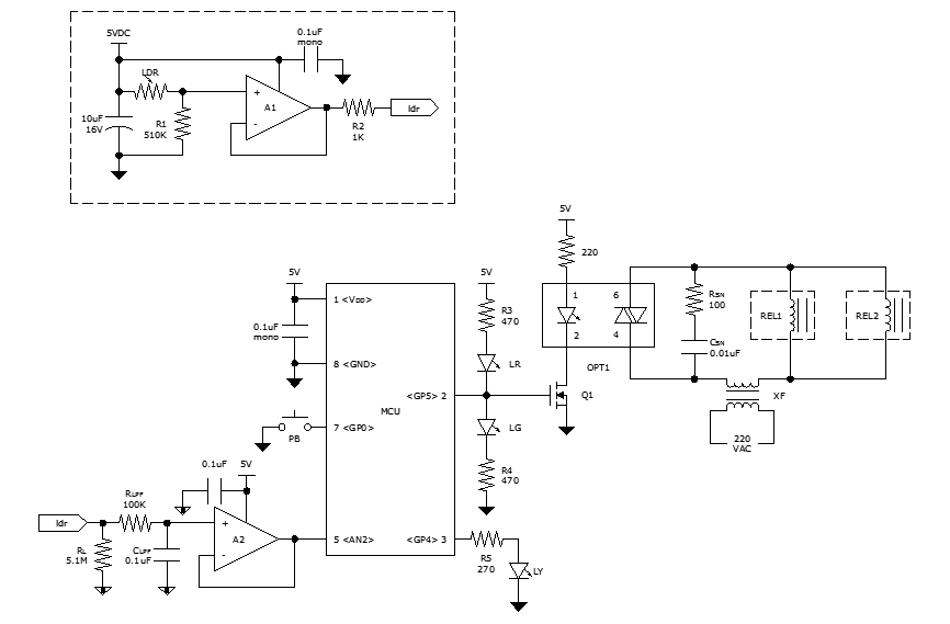
Microcontroller-based automatic night light circuit
While discussing an all-linear automatic night light circuit, it was mentioned that an MCU-based Automatic Night Light Controller (ANLC) was being tested. The firmware has been tweaked since then. Recently, the sensor was installed outdoors and connected to control 220VAC...
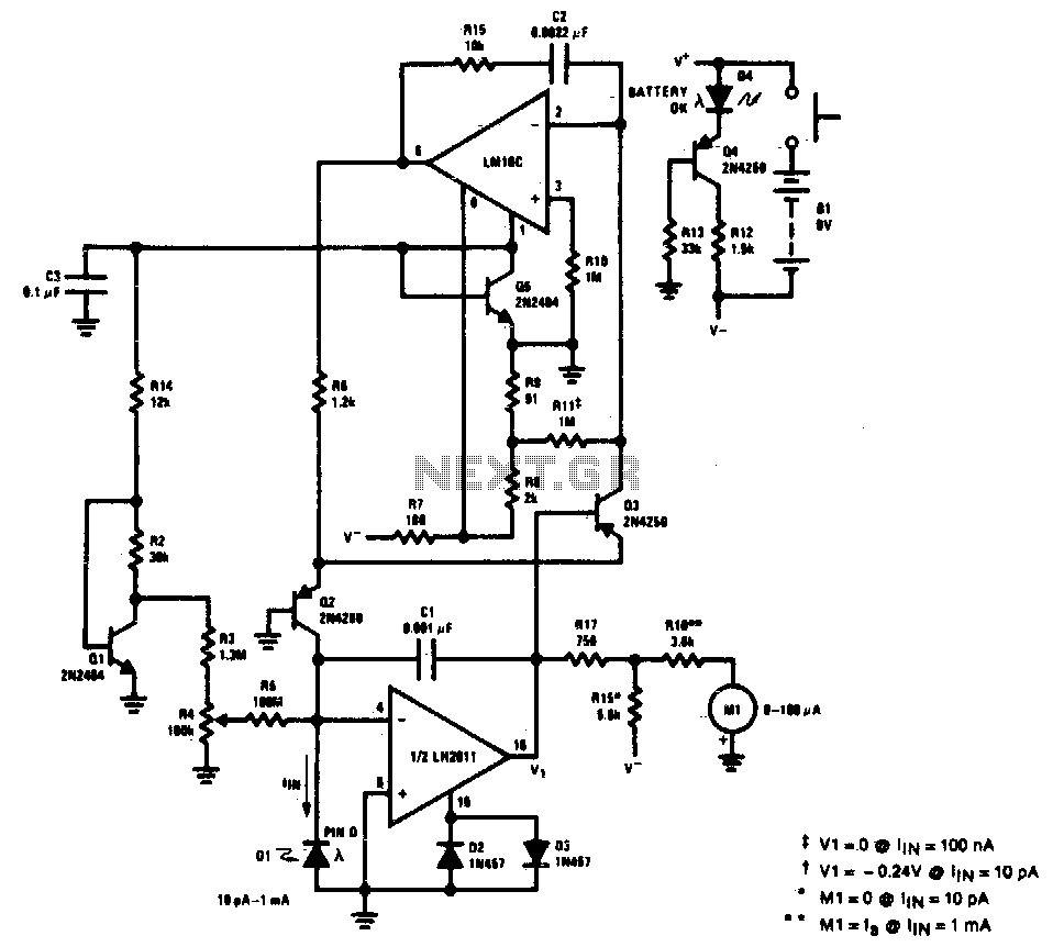
Light meter
This light meter features an eight-decade range. Bias current compensation enables an input current resolution of better than ±2 pA over a temperature range of 15 °C to 55 °C.
The light meter is designed to measure luminous intensity across a...
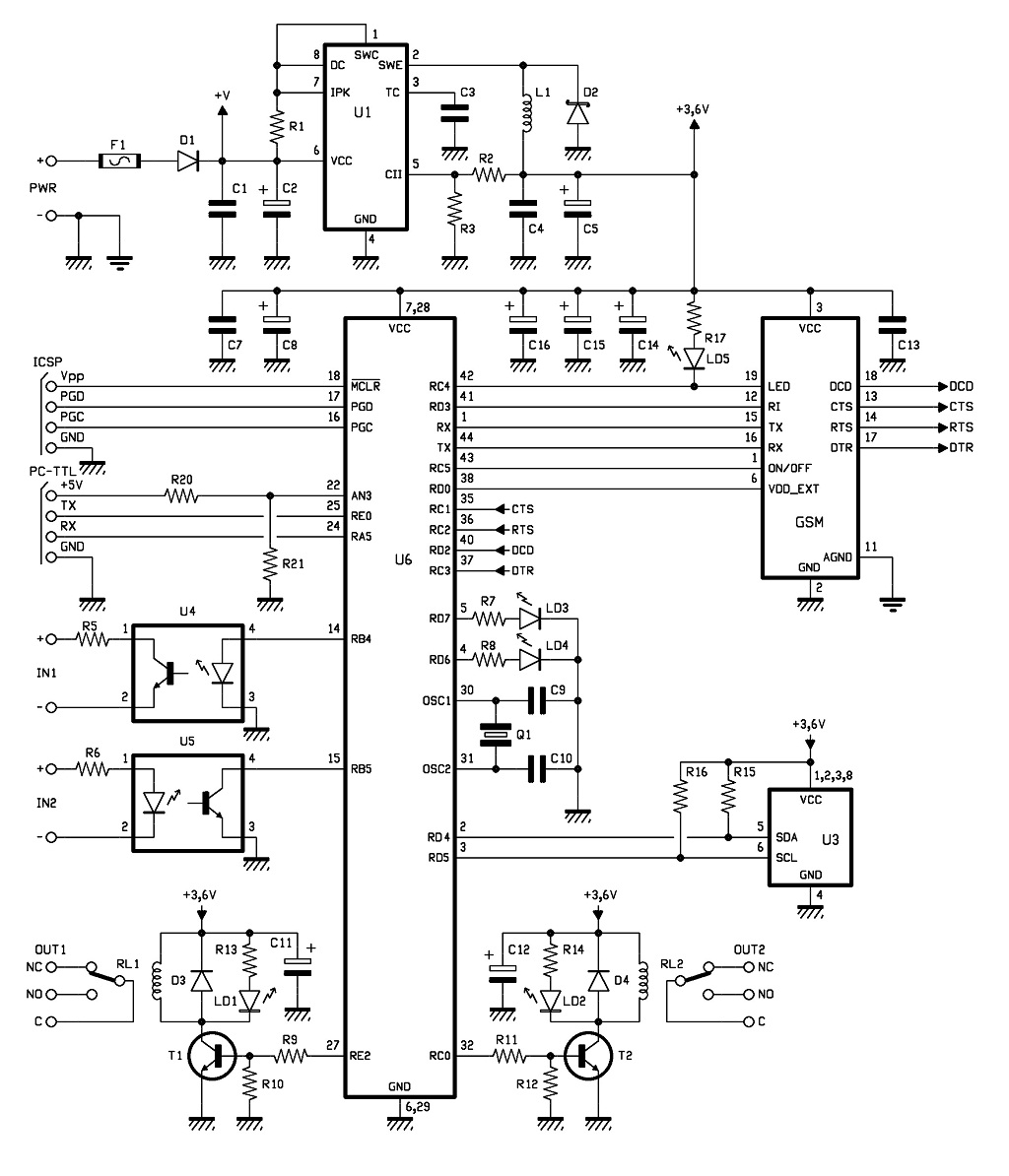
GSM Remote Control 2 IN and 2 OUT Part 2 Schematic
The control of the system is managed by a Microchip PIC18F46K20-I/PT microcontroller, which is programmed with firmware to oversee the activity of the GSM/GPRS module, monitor the logic conditions of two opto-isolated inputs, and send commands to two relays within...
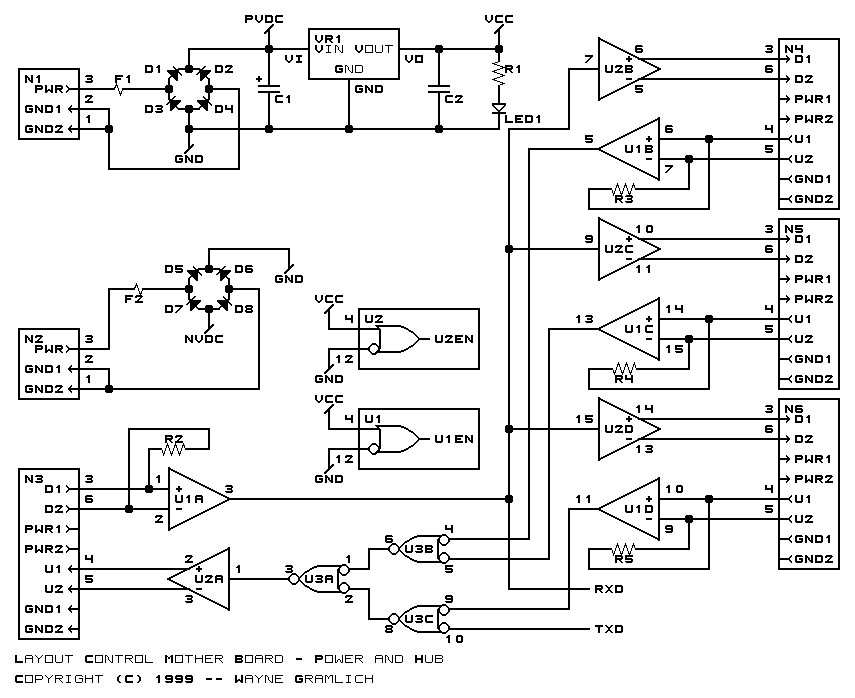
Layout Control Mother Board
The layout control motherboard is designed to facilitate the management of various sections of a layout. It features a microcontroller that connects to the MRNet bus and multiple slots for inexpensive control and sensor boards. All control and sensor boards...

microcontroller Generate a reset signal from a falling edge trigger
The microcontroller design features the microcontroller (MCU) in hibernation mode, which can only be awakened by a pulse (high-low-high) signal on the reset pin (active low). An accelerometer or an external real-time clock (RTC) serves as the wake-up source. The...
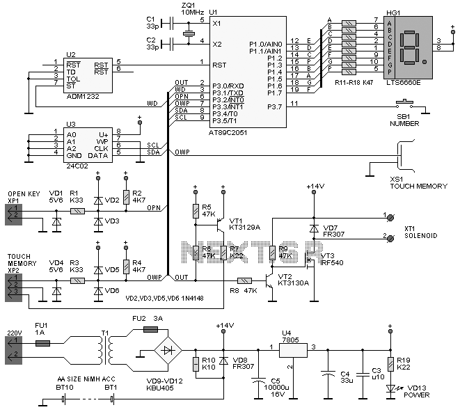
Analog to Digital Conversion
The project involves implementing analog-to-digital conversion using the ADC0804LCN 8-bit A/D converter. A circuit will be designed and programmed so that when an analog signal is input, the corresponding digital voltage is displayed on an LCD. Essentially, the circuit will...
The embedded microcontroller MC68HC912B32 background debugs the mode to design
The widespread application of Flash technology in microprocessors has led to significant advancements in the development and utilization of one-chip computers. Designers have transitioned from traditional in-circuit emulators (ICE) and JTAG interfaces to more cost-effective and user-friendly development methods. While...