


Plasma DisplayCircuit using ICL7135 A/D Converter
#ICL7135
#A/D converter
#plasma display
#analog to digital
#measurement
#instrumentation
#display driver
#integrating converter
#schematic
#circuit diagram
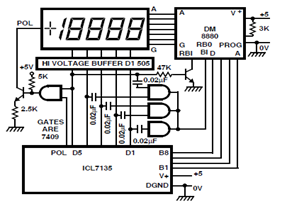
Description: A circuit diagram for driving a plasma-type display using the ICL7135 is presented in the schematic. This application highlights the versatility of this integrated Analog to Digital Converter device.
The ICL7135 is a high-precision, low-power, integrating Analog to Digital Converter (ADC) that is well-suited for applications requiring accurate digital representations of analog signals. In the context of driving a plasma-type display, the circuit utilizes the ICL7135 to convert the analog voltage levels generated by the display's control signals into a digital format that can be processed and displayed.
The schematic typically includes the following key components: the ICL7135 ADC, power supply connections, input signal conditioning circuitry, and output interfaces for driving the plasma display. The input stage may consist of operational amplifiers configured to amplify and filter the analog signals to ensure they are within the acceptable range for the ADC.
The ICL7135 operates by integrating the input voltage over a specified time period, allowing it to provide high-resolution measurements. Its output is a binary-coded decimal (BCD) format, which can be easily interfaced with digital display drivers. The circuit may also incorporate additional elements such as reference voltage sources, timing control circuits, and multiplexers to manage multiple input signals.
In summary, the circuit diagram for driving a plasma-type display using the ICL7135 ADC exemplifies the device's versatility and capability to provide accurate digital conversions for various applications, particularly in display technologies.A circuit diagram for driving a plasma-type display using ICL7135 is shown in the following schematic. This application is one of the wide versatility variety of this integrating Analog to Digital Converter device
The ICL7135 is a high-precision, low-power, integrating Analog to Digital Converter (ADC) that is well-suited for applications requiring accurate digital representations of analog signals. In the context of driving a plasma-type display, the circuit utilizes the ICL7135 to convert the analog voltage levels generated by the display's control signals into a digital format that can be processed and displayed.
The schematic typically includes the following key components: the ICL7135 ADC, power supply connections, input signal conditioning circuitry, and output interfaces for driving the plasma display. The input stage may consist of operational amplifiers configured to amplify and filter the analog signals to ensure they are within the acceptable range for the ADC.
The ICL7135 operates by integrating the input voltage over a specified time period, allowing it to provide high-resolution measurements. Its output is a binary-coded decimal (BCD) format, which can be easily interfaced with digital display drivers. The circuit may also incorporate additional elements such as reference voltage sources, timing control circuits, and multiplexers to manage multiple input signals.
In summary, the circuit diagram for driving a plasma-type display using the ICL7135 ADC exemplifies the device's versatility and capability to provide accurate digital conversions for various applications, particularly in display technologies.A circuit diagram for driving a plasma-type display using ICL7135 is shown in the following schematic. This application is one of the wide versatility variety of this integrating Analog to Digital Converter device
a d converter
This is the preliminary draft of the pH to 1-Wire converter schematic, with some component values still pending. The original circuit operates on 12 VDC, but since the A/D converter IC requires a 5 VDC supply, the circuit needs to...
High Speed A/D converter 12-bit
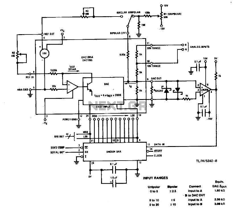
This system performs a complete conversion of 12 bits in both unipolar and bipolar modes. The converter is accurate to ±12-bit LSB with a typical gain temperature coefficient of 10 ppm/°C. In unipolar mode, the system operates within a range...
A/D Board
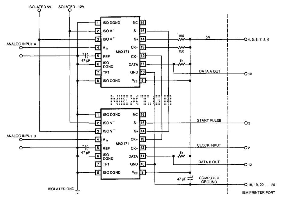
An IBM PC can operate two 12-bit A/D converters via its printer port. The converters' serial outputs utilize only two of the printer port's eight data lines (DATA A OUT, DATA B OUT). The IBM PC's printer port does not...
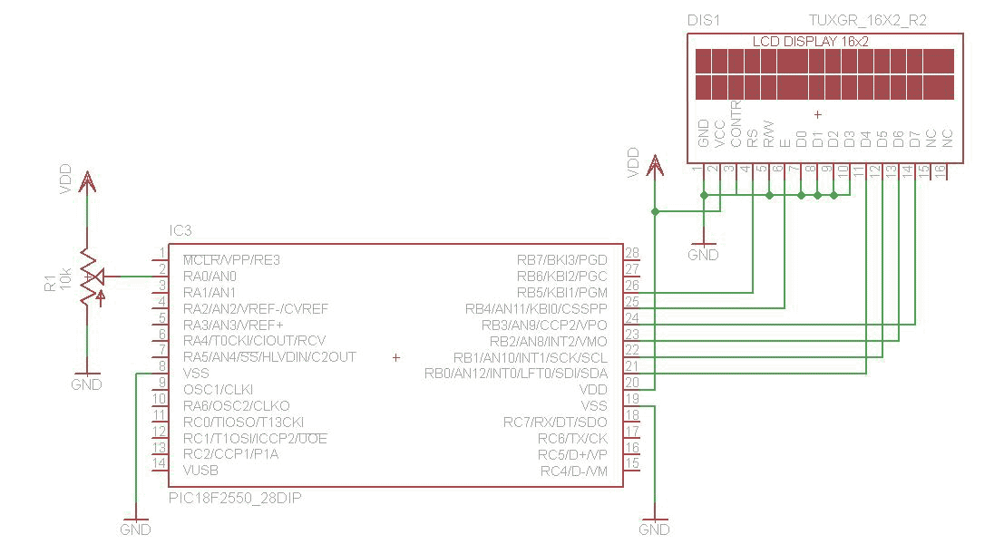
A/D converter 16Bit with LCD and PIC18F2550
The analog to digital converter (ADC) is commonly required in most of the projects. Analog voltage measurement can be done using the ADC hardware built in together in a PIC. The picture below shows a simple setup for measuring the...
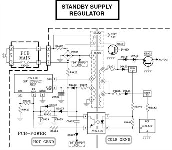
Need to have the circuit schematic for LG 29SA1RL model
The schematic is in PDF format and cannot be sent through this site. It is recommended to check a specific website that contains various schematics, including older posts that might have the schematic needed. A WS-55807 model is experiencing issues...
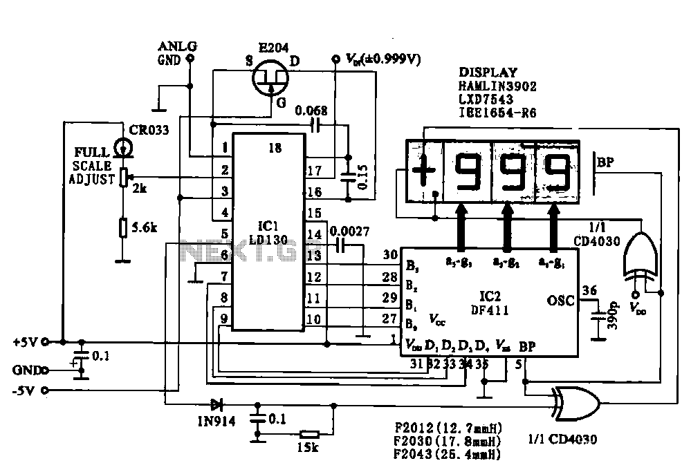
Display driver circuit digital voltmeter
This circuit illustrates a display driving system for a digital voltmeter. The liquid crystal display (LCD) does not emit light by itself; it relies on external incident light for visibility. The integrated circuit (IC) LD130 serves as an input voltage...
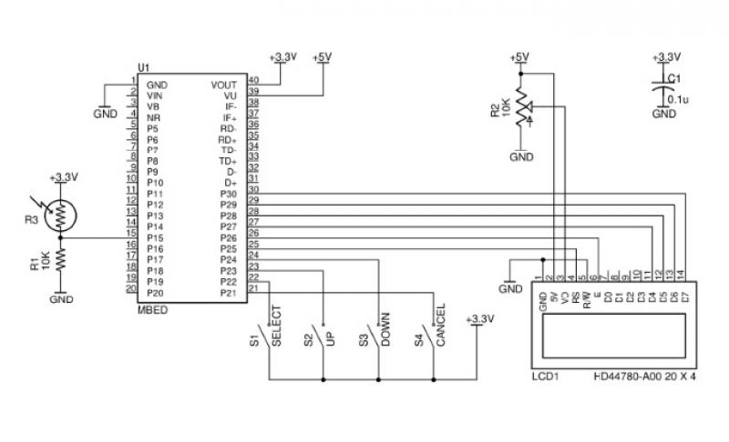
Advances in Measurement & Sensor Tech
This issue features articles on various measurement and sensor-related embedded design projects. Readers are encouraged to attempt similar projects and share their results. Starting on page 14, Petre Tzvetanov Petrov describes a multilevel audible logical probe design. Petrov notes that...
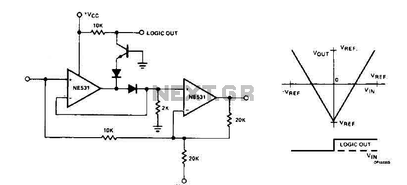
Cyclic A/D converter circuit
The cyclic converter is composed of a series of identical stages, each stage detecting the polarity of the input. The reference voltage, V_REF, is subtracted from the double entry, and the remaining value is processed if the polarity is correct....
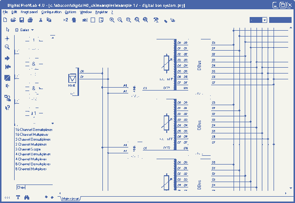
Digital-ProfiLab 4.0
Digital-ProfiLab was designed for measurement and control applications, combining features like circuit and logic simulation, front panel design, and hardware control to one powerful tool. Incoming signals from external devices may be processed and displayed. A circuit editor is used...