


Polyphase energy metering using ic
#polyphase energy metering
#ADE7762
#3 phase power
#energy measurement
#digital meter
#power consumption
#home energy monitoring
#current sensor
#voltage sensor
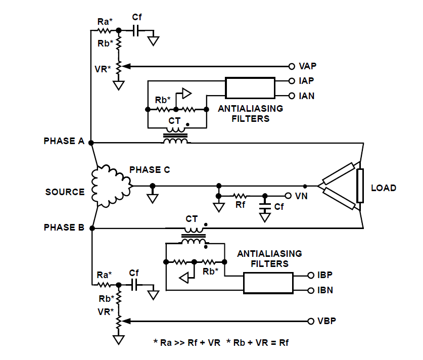
Description: How can a circuit be built for digital readout of three-phase power consumption in a home using a chip like ADE7762? There is an interest in polyphase energy metering.
To construct a circuit for digital readout of three-phase power consumption utilizing the ADE7762 energy metering IC, several key components and considerations must be taken into account. The ADE7762 is designed for high-accuracy energy measurement in polyphase systems, making it suitable for residential applications where monitoring power consumption across multiple phases is necessary.
The circuit will typically consist of the following components:
1. **ADE7762 IC**: This chip will serve as the core of the energy metering circuit. It measures voltage and current across the three phases and calculates power consumption, voltage, current, and energy values.
2. **Current Transformers (CTs)**: For each phase, current transformers will be used to sense the current flowing through the wires. These should be selected based on the expected load and should have a suitable turns ratio to provide a measurable output for the ADE7762.
3. **Voltage Divider**: To measure the voltage of each phase, a voltage divider circuit is necessary. This will scale down the high voltage levels to a range that the ADE7762 can handle safely. The resistors in the divider must be chosen carefully to ensure accuracy and safety.
4. **Microcontroller**: A microcontroller may be included to interface with the ADE7762. It will read the digital output from the ADE7762 and can be programmed to display the data on an LCD or send it to a remote monitoring system via wireless communication.
5. **Power Supply**: The circuit will require a stable power supply to operate the ADE7762 and the microcontroller. This can be achieved using a dedicated power supply circuit or by utilizing a switching power supply that can convert the mains voltage to a lower DC voltage.
6. **Filtering Capacitors**: Capacitors should be used in the circuit to filter out noise from the power lines, ensuring that the measurements taken by the ADE7762 are accurate and reliable.
7. **PCB Design**: The layout of the printed circuit board (PCB) is crucial for minimizing interference and ensuring accurate measurements. Careful placement of components and routing of traces will help in achieving optimal performance.
8. **Calibration**: After assembling the circuit, calibration is essential to ensure that the readings from the ADE7762 reflect actual power consumption accurately. This may involve comparing the readings to a known reference and adjusting the circuit as necessary.
By integrating these components and following best practices in circuit design and assembly, a reliable digital readout system for three-phase power consumption can be achieved using the ADE7762. This system will enable homeowners to monitor their energy usage effectively, potentially leading to better energy management and cost savings.how do I build a circuit for digital dead out of 3 phase power consumption in home using any chip like ADE7762 ? I am interested in Polyphase Energy Metering using a..
To construct a circuit for digital readout of three-phase power consumption utilizing the ADE7762 energy metering IC, several key components and considerations must be taken into account. The ADE7762 is designed for high-accuracy energy measurement in polyphase systems, making it suitable for residential applications where monitoring power consumption across multiple phases is necessary.
The circuit will typically consist of the following components:
1. **ADE7762 IC**: This chip will serve as the core of the energy metering circuit. It measures voltage and current across the three phases and calculates power consumption, voltage, current, and energy values.
2. **Current Transformers (CTs)**: For each phase, current transformers will be used to sense the current flowing through the wires. These should be selected based on the expected load and should have a suitable turns ratio to provide a measurable output for the ADE7762.
3. **Voltage Divider**: To measure the voltage of each phase, a voltage divider circuit is necessary. This will scale down the high voltage levels to a range that the ADE7762 can handle safely. The resistors in the divider must be chosen carefully to ensure accuracy and safety.
4. **Microcontroller**: A microcontroller may be included to interface with the ADE7762. It will read the digital output from the ADE7762 and can be programmed to display the data on an LCD or send it to a remote monitoring system via wireless communication.
5. **Power Supply**: The circuit will require a stable power supply to operate the ADE7762 and the microcontroller. This can be achieved using a dedicated power supply circuit or by utilizing a switching power supply that can convert the mains voltage to a lower DC voltage.
6. **Filtering Capacitors**: Capacitors should be used in the circuit to filter out noise from the power lines, ensuring that the measurements taken by the ADE7762 are accurate and reliable.
7. **PCB Design**: The layout of the printed circuit board (PCB) is crucial for minimizing interference and ensuring accurate measurements. Careful placement of components and routing of traces will help in achieving optimal performance.
8. **Calibration**: After assembling the circuit, calibration is essential to ensure that the readings from the ADE7762 reflect actual power consumption accurately. This may involve comparing the readings to a known reference and adjusting the circuit as necessary.
By integrating these components and following best practices in circuit design and assembly, a reliable digital readout system for three-phase power consumption can be achieved using the ADE7762. This system will enable homeowners to monitor their energy usage effectively, potentially leading to better energy management and cost savings.how do I build a circuit for digital dead out of 3 phase power consumption in home using any chip like ADE7762 ? I am interested in Polyphase Energy Metering using a..
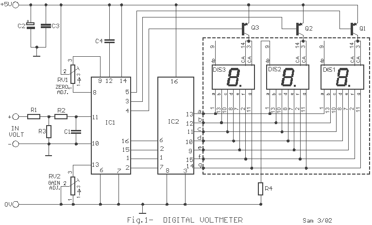
Digital Volt and Ampere meter
The circuit does not present particular difficulties for somebody that has a small experience. The two circuits are the himself, with a small difference only in their input, when they have they measure voltage or current and in connection that...
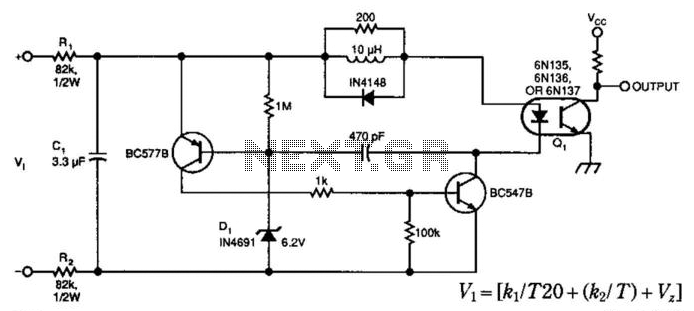
Isolated Voltage Sensor
A simple voltage-controlled oscillator (VCO), coupled to instrumentation by an optoisolator, allows for the measurement of high voltages. The component values are suitable for a 0 to 600 V input range, with power dissipation in resistors RI and R2 setting...
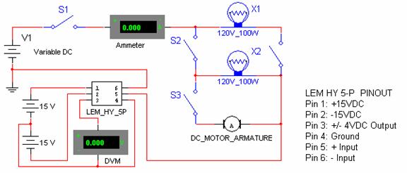
Current Sensor Testing and calibration
Connect the negative side of the positive supply to the positive side of the negative supply to create a ±15 VDC. This junction serves as the ground for the transducer, ensuring a balanced voltage. Continue the experiment by switching off...
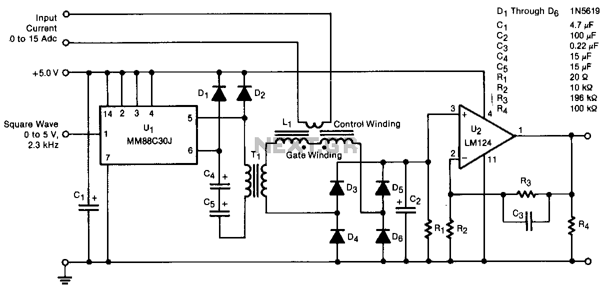
Low-power-magnetic-current-sensor
A transducer senses direct current magnetically, providing isolation between the input and the output. The detecting and isolating element is a saturable reactor, through which the input current to be measured passes via a one-turn control coil. The transducer offers...
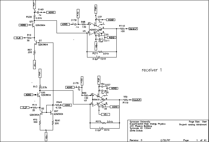
Chip carrier test
VA-RICH Power consumption: -2V current draws 34 mA, +2V current draws 5 mA. Total power consumption is 68 mW. Spark protection: Spark protection works, but the spark current burns the trace from pad to input transistor, which makes the channel...
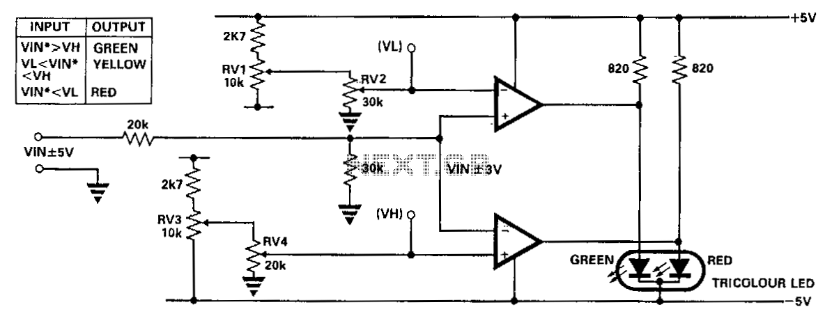
Simplified-voltage-level-sensor
This circuit utilizes a single junction component, either one LM393 dual comparator or one LM339 quad comparator. Resistors RV1 and RV3 are responsible for establishing the full-scale reference voltage, while resistors RV2 and RV4 are used to set the switching...
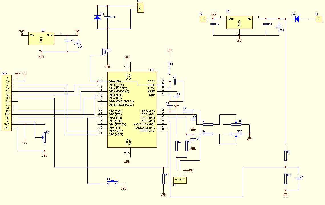
Voltage, Ampere Digital meter
This multimeter was designed to measure output voltage and current in a PSU, where the current sense shunt resistor is connected in series with load at the negative voltage rail. It needs only one supply voltage that can be acquired...
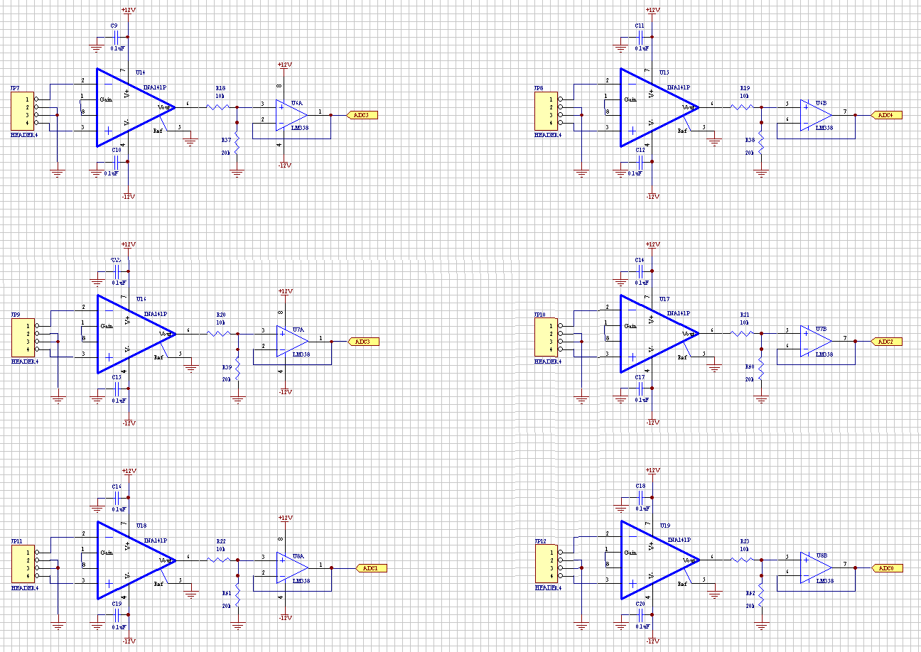
Current Sensor Board
The Current Sensor Board features an Atmel AVR AT90S8535 microcontroller operating at 8 MHz. It samples six ADC current inputs and utilizes the remaining two ADC inputs for controlling an integrating charge counter. The processed results are encapsulated into data...
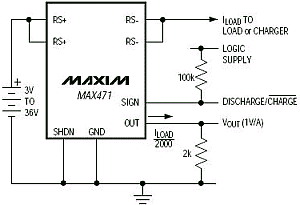
Robot Tutorials current sensor
Current sensing involves detecting the amount of current being used by a specific circuit or device. It is particularly useful for assessing the power consumption of various components within a robotic system. Although not commonly required in robotics, current sensing...