


Radiation Indicator
#radiation detector
#SBM-20
#voltage rectifier
#diodes
#capacitors
#AC power
#sensor circuit
#DIY instrument
#radiation measurement
#high voltage
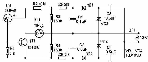
Description: Measuring radiation does not require expensive factory-made instruments. A simple device can be constructed using a radiation detector, such as the SBM-20 or a similar type. The circuit operates on 220 volts AC at 50/60Hz. The double-voltage rectifier circuit consists of diodes VD1 and VD2, along with capacitors C1 and C2. The DC voltage across capacitors C1 and C2 is approximately 310 V each, resulting in a total rectified voltage of about 620 V. This voltage is then divided down to 400 V using a voltage divider composed of resistors R5 and R3 for capacitor C1, and R6 and R4 for capacitor C2. Consequently, the voltage across resistors R3 and R4 is around 200 V. The Geiger-Muller counter BD1 is powered by 400 V, while the neon lamp HL1, which serves as an indicator, operates at 200 V. The neon lamp HL1 illuminates only when transistor VT1 is activated, which occurs when radiation ionizes the gas within the Geiger-Muller tube BD1. Resistor R1 assists in turning off transistor VT1 in the absence of radiation, while resistor R2 limits the base current of transistor VT1 during radiation detection. In the absence of radiation sources, the Geiger-Muller counter generates 20 to 30 electrical pulses per minute due to natural background radiation. As a result, transistor VT1 opens briefly, causing the neon lamp HL1 to flash every 2 to 3 seconds, albeit without a strict pattern. As radiation levels increase, the frequency of the neon lamp HL1's flashes also rises. This can be demonstrated by bringing a phosphorescent Christmas toy near the counter. Under very high radiation levels, the neon lamp HL1 remains continuously lit. The circuit can be modified for operation at 110 volts AC at 50/60Hz, as illustrated in figure 2, by adding diodes D3 and D4, capacitors C3 and C5 (0.5 F x 400V), and changing the values of resistors R3 and R4 to 150k.
The described radiation measurement circuit utilizes a Geiger-Muller counter to detect ionizing radiation. The circuit is powered by a standard AC supply and employs a double-voltage rectifier configuration to convert AC to DC, which is essential for powering the high-voltage components of the Geiger-Muller tube. The rectifier's output voltage is effectively managed through a voltage divider, ensuring that the Geiger-Muller counter receives the necessary 400 V for operation while maintaining the neon lamp's voltage at a safe 200 V.
The operation of the Geiger-Muller counter is based on the principle of ionization. When radiation passes through the Geiger-Muller tube, it ionizes the gas inside, allowing current to flow and activating transistor VT1. This transistor acts as a switch, controlling the neon lamp HL1. The flashing of the neon lamp serves as a visual indicator of radiation levels, with the frequency of the flashes correlating to the intensity of the detected radiation. The circuit's design also incorporates safety features, such as resistor R1, which ensures that the transistor turns off when no radiation is present, and resistor R2, which protects the transistor from excessive current.
The flexibility of the circuit is highlighted by its ability to be modified for different AC voltage ratings, making it adaptable for various applications. The inclusion of additional components in the modified version for 110 volts AC demonstrates the circuit's versatility and ease of adaptation for different operating environments. Overall, this simple yet effective design provides a practical solution for radiation detection, suitable for educational purposes, hobbyist projects, or basic radiation monitoring.Measuring the radiation can be made not only with expensive factory-made instrument. The simplest device (see Figure 1), can be build if you have a counter (radiation detector) type SBM-20 or similar. The circuit is powered by a 220 volts AC 50/60Hz. The double-voltage rectifier circuit is made of diodes VD1, VD2, and capacitors C1, C2. The DC vol tage across the capacitors C1 and C2 is about 310 V on each one, so the total voltage of the rectifier is approximately 620 V. The voltage 620 V is divided by a voltage divider to the 400 V. The resistors R5 and R3 forms the voltage divider for the voltage across the capacitor C1, and the resistors R6 and R4 - for the voltage across the capacitor C2.
That is why the voltage across the resistors R3 and R4 is about 200 V. Thus, the Geiger-Muller counter BD1 (radiation detector) is powered by 400 V, while the neon lamp HL1 (an indicator) is powered only by 200 V. The neon lamp HL1 is lit only when transistor VT1 is on, and this transistor is on when the radiation ionizes the gas inside the Geiger-Mueller tube BD1.
The resistor R1 helps to switch off the transistor VT1 when there is no radiation, and the resistor R2 limits the base current of the transistor VT1 when there is the radiation. When there is no radiation sources around, the Geiger-Muller produces 20. 30 electrical pulses in one minute because of the natural background radiation. Consequently, the transistor VT1 will be open for a short time - the neon lamp HL1 flashes every 2. 3 seconds, but without strict periodicity. When the radiation levels getting higher, the neon lamp HL1 flashes more frequently. This can be verified by bringing to the counter the usual Christmas toy, covered in phosphorus. When the radiation level is very high, the neon lamp HL1 is lit continuously. The circuit can be modified for 110 volts AC 50/60Hz, as shown in figure 2. In the basic circuit has been added diodes D3, D4, capacitors C3, C5 (0. 5 F x 400V), and the values of resistors R3, R4 has been changed to 150k.
The described radiation measurement circuit utilizes a Geiger-Muller counter to detect ionizing radiation. The circuit is powered by a standard AC supply and employs a double-voltage rectifier configuration to convert AC to DC, which is essential for powering the high-voltage components of the Geiger-Muller tube. The rectifier's output voltage is effectively managed through a voltage divider, ensuring that the Geiger-Muller counter receives the necessary 400 V for operation while maintaining the neon lamp's voltage at a safe 200 V.
The operation of the Geiger-Muller counter is based on the principle of ionization. When radiation passes through the Geiger-Muller tube, it ionizes the gas inside, allowing current to flow and activating transistor VT1. This transistor acts as a switch, controlling the neon lamp HL1. The flashing of the neon lamp serves as a visual indicator of radiation levels, with the frequency of the flashes correlating to the intensity of the detected radiation. The circuit's design also incorporates safety features, such as resistor R1, which ensures that the transistor turns off when no radiation is present, and resistor R2, which protects the transistor from excessive current.
The flexibility of the circuit is highlighted by its ability to be modified for different AC voltage ratings, making it adaptable for various applications. The inclusion of additional components in the modified version for 110 volts AC demonstrates the circuit's versatility and ease of adaptation for different operating environments. Overall, this simple yet effective design provides a practical solution for radiation detection, suitable for educational purposes, hobbyist projects, or basic radiation monitoring.Measuring the radiation can be made not only with expensive factory-made instrument. The simplest device (see Figure 1), can be build if you have a counter (radiation detector) type SBM-20 or similar. The circuit is powered by a 220 volts AC 50/60Hz. The double-voltage rectifier circuit is made of diodes VD1, VD2, and capacitors C1, C2. The DC vol tage across the capacitors C1 and C2 is about 310 V on each one, so the total voltage of the rectifier is approximately 620 V. The voltage 620 V is divided by a voltage divider to the 400 V. The resistors R5 and R3 forms the voltage divider for the voltage across the capacitor C1, and the resistors R6 and R4 - for the voltage across the capacitor C2.
That is why the voltage across the resistors R3 and R4 is about 200 V. Thus, the Geiger-Muller counter BD1 (radiation detector) is powered by 400 V, while the neon lamp HL1 (an indicator) is powered only by 200 V. The neon lamp HL1 is lit only when transistor VT1 is on, and this transistor is on when the radiation ionizes the gas inside the Geiger-Mueller tube BD1.
The resistor R1 helps to switch off the transistor VT1 when there is no radiation, and the resistor R2 limits the base current of the transistor VT1 when there is the radiation. When there is no radiation sources around, the Geiger-Muller produces 20. 30 electrical pulses in one minute because of the natural background radiation. Consequently, the transistor VT1 will be open for a short time - the neon lamp HL1 flashes every 2. 3 seconds, but without strict periodicity. When the radiation levels getting higher, the neon lamp HL1 flashes more frequently. This can be verified by bringing to the counter the usual Christmas toy, covered in phosphorus. When the radiation level is very high, the neon lamp HL1 is lit continuously. The circuit can be modified for 110 volts AC 50/60Hz, as shown in figure 2. In the basic circuit has been added diodes D3, D4, capacitors C3, C5 (0. 5 F x 400V), and the values of resistors R3, R4 has been changed to 150k.
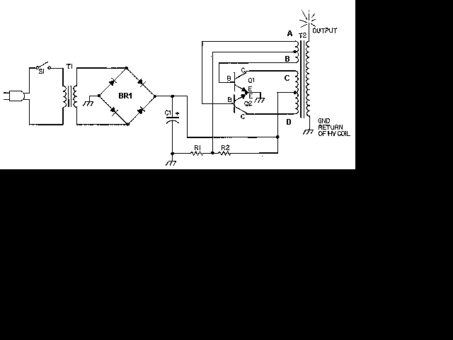
hv generator circuit
This circuit is designed to demonstrate high frequency and high voltage, capable of producing approximately 30kV, depending on the transformer utilized. It is cost-effective and straightforward to construct, primarily using a standard TV flyback transformer. This circuit can power lasers,...
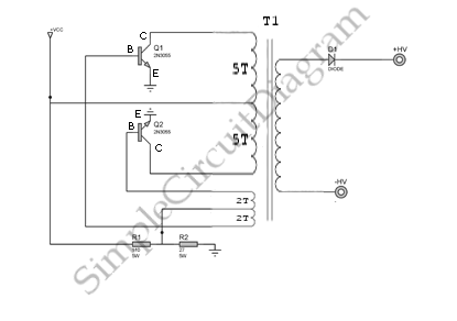
High Voltage Inverter
This is a simple high-voltage inverter circuit. It uses an NPN transistor type 2N3055. This circuit is designed to invert low voltage to high voltage.
The high-voltage inverter circuit utilizing the 2N3055 NPN transistor serves as an effective means to convert...
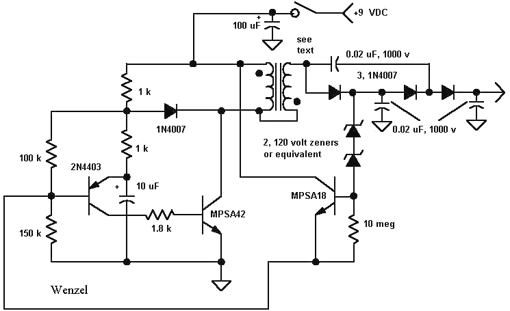
simulation Understanding a high voltage generator circuit
A high voltage power supply DC converter that operates between 3V to 500V has been suggested for use with Geiger tubes. However, during simulation, the output remained at nearly 9V, which matches the input voltage. The schematic drawn has only...
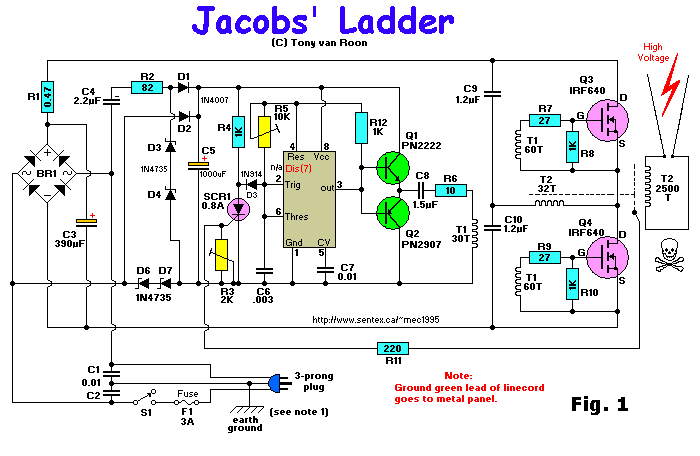
Jacobs Ladder
Construct this engaging Jacob's Ladder to observe electric arcs ascending the ladder and dissipating into the atmosphere. It operates using a sophisticated 12,000-volt power supply. The author, Robert Iannini, notes that electric arcs have long captivated and intimidated people, manifesting...

Filament and Control Power Supplies
AC power is supplied through AC Fuse F1 and Power On/Off switch S1 to a 6.3V filament transformer T1. An additional safety feature, Fuse F2, is included, as a short circuit to the filament transformer may not trigger the main...
Capacitors
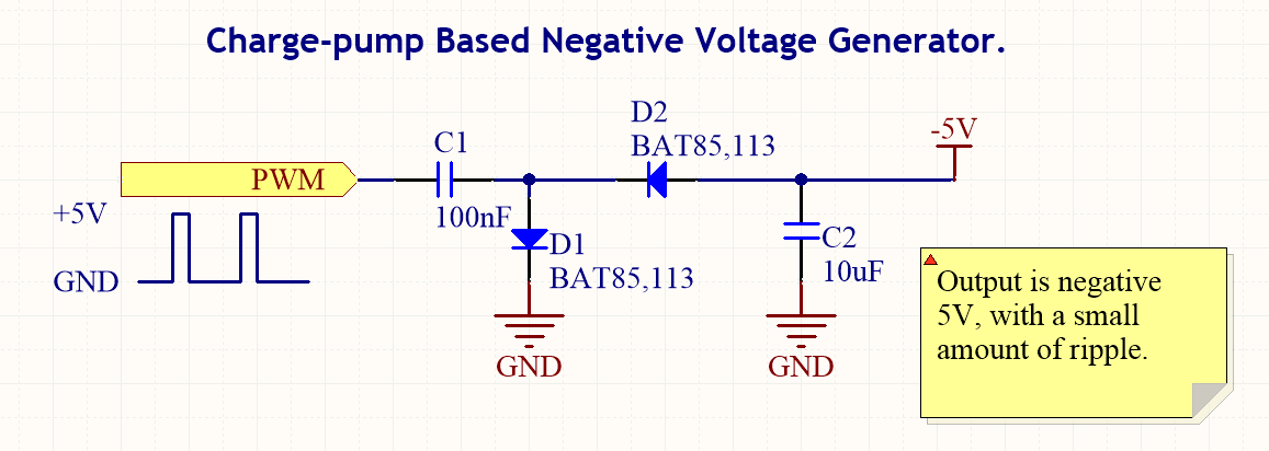
Capacitor types, their uses, formulas for common capacitance calculations, descriptions of charge pumps, information on dielectric soakage, and how to repair.
Capacitors are essential components in electronic circuits, serving various functions depending on their type and application. The primary types of...
Salvaging Interesting Gadgets Components and Subsystems
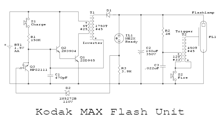
The high voltage power supply is likely capable of delivering between 12 to 30 kVDC at a current of 1 or 2 mA. This output is suitable for various high voltage applications, including experiments, plasma globes, negative ion and ozone...
diodes on electromechanical vane display
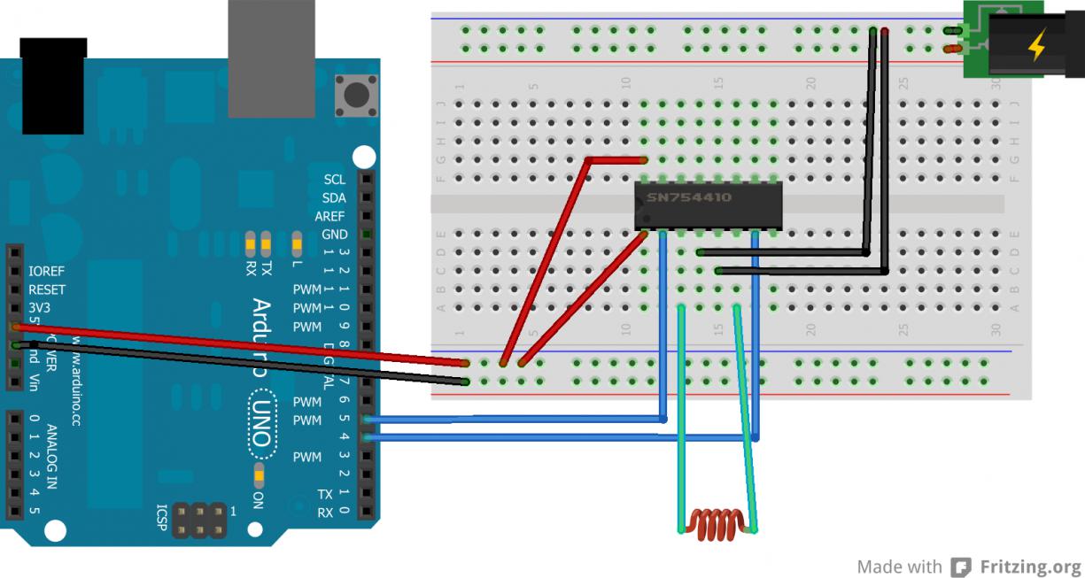
A newcomer to electronics has recently acquired several electromechanical seven-segment vane displays and seeks assistance.
Electromechanical seven-segment vane displays are devices commonly used for visual representation of numerical data. They consist of a series of segments arranged in a figure-eight pattern,...
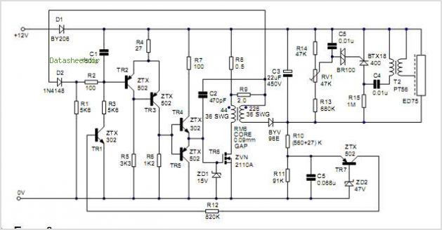
High Voltage Generation For Xenon Tube Applications
Power demand in portable designs can require, in specific applications, more than 1 A. A method involves paralleling two DC to DC converters on the same load instead of using a single higher current converter with a lower switching frequency....