


ramped magnetic field circuit for a miniature mass spectrometer
#Arduino
#DAC
#mass spectrometer
#magnetic field
#digital ramp
#8-bit
#timing
#scientific instrumentation
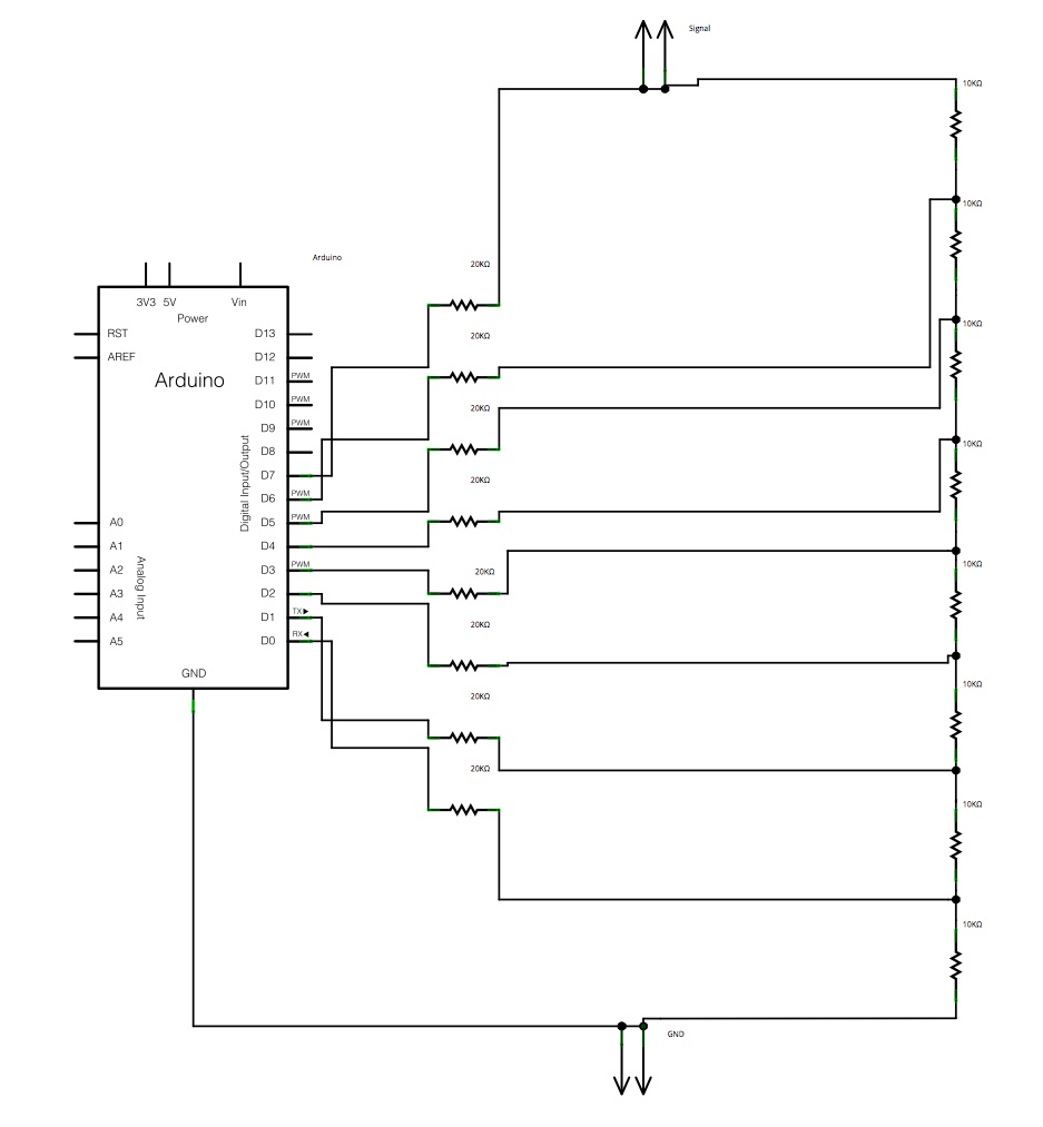
Description: The main concept is to space the time intervals to increment the DAC output values. There are 256 levels since there are 8 digital outputs from the Arduino board. Therefore, for an 8-bit resolution and a 50-second ramp time, the method to generate a digital ramp waveform is to increment each level every (50/256) seconds. Regardless of the coding approach, a DAC is necessary to convert the digital signal to an analog signal. An R-2R ladder is a simple and cost-effective method for digital-to-analog conversion, utilizing a repetitive arrangement of precision resistors in a ladder configuration. A schematic of the R-2R ladder DAC circuit is drawn using Fritzing.
The R-2R ladder DAC is a widely used circuit for converting digital signals into analog voltages. This circuit employs a network of resistors arranged in a specific manner to achieve the desired output. The R-2R ladder consists of two resistor values: R and 2R. Each bit of the digital input corresponds to a switch that connects either to a reference voltage (V_ref) or ground (0V).
In the context of an 8-bit DAC, there are 8 digital inputs, each controlling a switch. When a switch is connected to V_ref, it contributes to the output voltage, while connecting to ground eliminates its contribution. The output voltage is calculated based on the binary representation of the inputs, where each bit represents a different weight in the overall voltage calculation. The most significant bit (MSB) has the highest weight, while the least significant bit (LSB) has the lowest.
For the timing aspect, with a specified ramp time of 50 seconds, the circuit must increment the output voltage level every (50/256) seconds, allowing for a smooth transition across all 256 levels. This timing can be managed using a microcontroller, such as an Arduino, which generates the necessary control signals to toggle the switches in the R-2R ladder.
The precision of this DAC largely depends on the tolerance of the resistors used. It is essential to use high-precision resistors to ensure that the output voltage levels are accurate and consistent. Furthermore, the circuit can be enhanced by adding a low-pass filter at the output to smooth out any rapid fluctuations in voltage, resulting from the switching of the digital inputs.
In summary, the R-2R ladder DAC provides an efficient means of converting digital signals to analog voltages, with the Arduino controlling the timing and sequence of the output levels to create a smooth ramp waveform. The schematic representation created using Fritzing visually illustrates the arrangement of the resistors and the connections to the Arduino, facilitating a clear understanding of the circuit's operation.The general idea is to space the time internals to increment the DAC output values. There would be 256 levels since there are 8 digital outputs from the Arduino board. Therefore, for an 8-bit, 50s ramp time for example, the way to generate a digital ramp waveform is to increment every level per (50/256)s. No matter what the code will be, a DAC is required to convert digital signal to analog signal. An R-2R Ladder is a simple and inexpensive way to perform digital-to-analog conversion, using repetitive arrangements of precision resistor networks in a ladder-like configuration. Now I use fritzing to draw the schematic of R-2R ladder DAC circuit.
The R-2R ladder DAC is a widely used circuit for converting digital signals into analog voltages. This circuit employs a network of resistors arranged in a specific manner to achieve the desired output. The R-2R ladder consists of two resistor values: R and 2R. Each bit of the digital input corresponds to a switch that connects either to a reference voltage (V_ref) or ground (0V).
In the context of an 8-bit DAC, there are 8 digital inputs, each controlling a switch. When a switch is connected to V_ref, it contributes to the output voltage, while connecting to ground eliminates its contribution. The output voltage is calculated based on the binary representation of the inputs, where each bit represents a different weight in the overall voltage calculation. The most significant bit (MSB) has the highest weight, while the least significant bit (LSB) has the lowest.
For the timing aspect, with a specified ramp time of 50 seconds, the circuit must increment the output voltage level every (50/256) seconds, allowing for a smooth transition across all 256 levels. This timing can be managed using a microcontroller, such as an Arduino, which generates the necessary control signals to toggle the switches in the R-2R ladder.
The precision of this DAC largely depends on the tolerance of the resistors used. It is essential to use high-precision resistors to ensure that the output voltage levels are accurate and consistent. Furthermore, the circuit can be enhanced by adding a low-pass filter at the output to smooth out any rapid fluctuations in voltage, resulting from the switching of the digital inputs.
In summary, the R-2R ladder DAC provides an efficient means of converting digital signals to analog voltages, with the Arduino controlling the timing and sequence of the output levels to create a smooth ramp waveform. The schematic representation created using Fritzing visually illustrates the arrangement of the resistors and the connections to the Arduino, facilitating a clear understanding of the circuit's operation.The general idea is to space the time internals to increment the DAC output values. There would be 256 levels since there are 8 digital outputs from the Arduino board. Therefore, for an 8-bit, 50s ramp time for example, the way to generate a digital ramp waveform is to increment every level per (50/256)s. No matter what the code will be, a DAC is required to convert digital signal to analog signal. An R-2R Ladder is a simple and inexpensive way to perform digital-to-analog conversion, using repetitive arrangements of precision resistor networks in a ladder-like configuration. Now I use fritzing to draw the schematic of R-2R ladder DAC circuit.
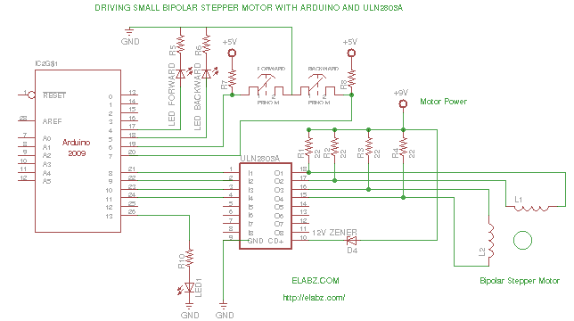
Driving a Bipolar Stepper Motor with Arduino and ULN2803AG
While preparing to disassemble several broken DVD-RW drives obtained from an eBay seller, the idea arose to create a testing platform for the bipolar stepper motors that would be salvaged from these drives. A collection of ULN2803AG Eight Darlington Transistor...
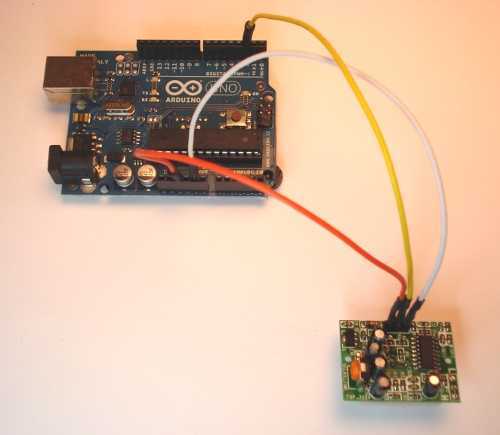
Arduino Motion Sensor
Give your Arduino board a motion sense around it! Use any Arduino board: Uno, Mega, Duemilanove etc.
To implement motion sensing capabilities with an Arduino board, a typical circuit would involve the integration of a passive infrared (PIR) sensor, which is...
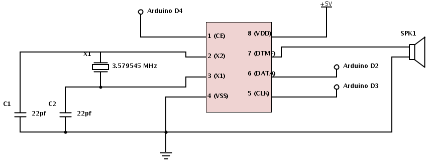
Arduino Producing DTMF Tones
The project involves teaching an Arduino to generate DTMF (Dual-Tone Multi-Frequency) tones using the HT9000A DTMF chip. These tones are the familiar "touch tones" used in telephone systems. The output volume from the chip is low, suggesting the need for...
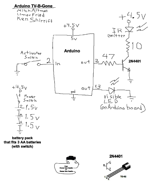
Improved Arduino TV-B-Gone
The TV-B-Gone is a compact infrared remote capable of turning off nearly any television. Previously, the TV-B-Gone software was adapted for use with the Arduino platform. For further details regarding this adaptation and its functionality, refer to the earlier post...
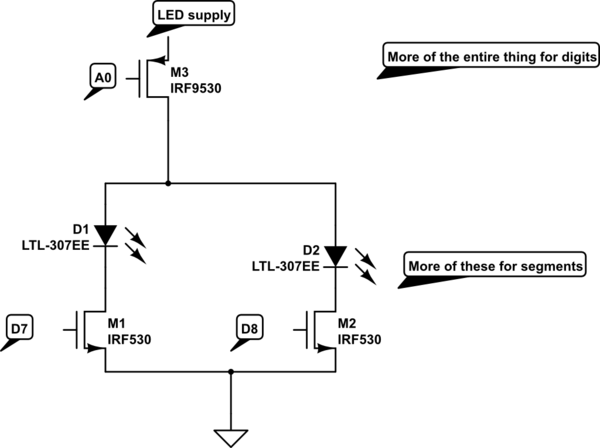
arduino How can I display a scoreboard on stage for a play
A scoreboard is located in the center of the room, which will be controlled from backstage. The scoreboard features two individual 3-digit numbers. Whenever the score changes, a sound will be emitted. The simplest, most efficient, and cost-effective solution identified...
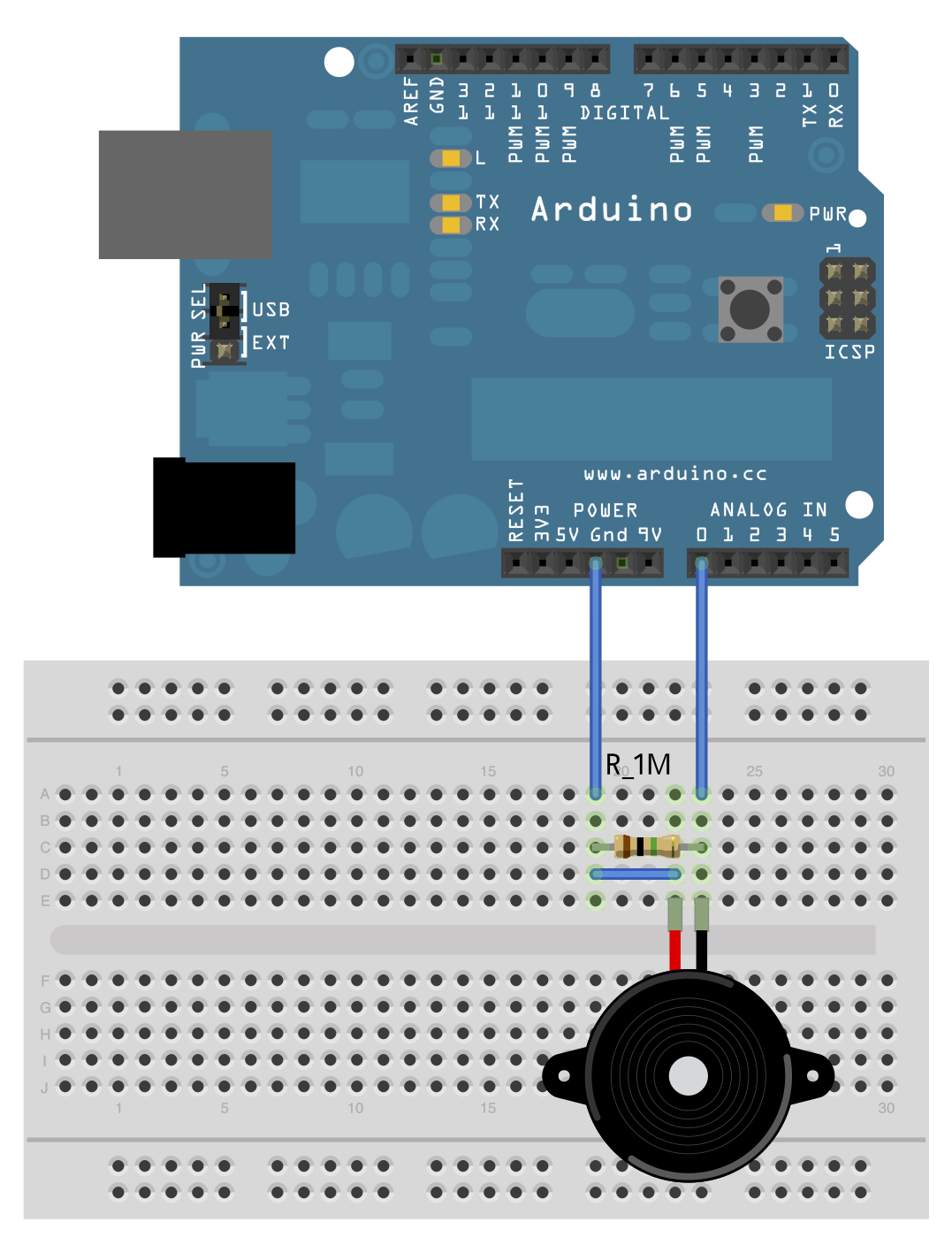
Arduino driving a motor with MC33887 Motor Driver
Posts about a tutorial written by Harandi and Amirsab.
The content refers to a series of instructional posts focused on a particular tutorial authored by individuals identified as Harandi and Amirsab. These posts likely encompass various topics related to electronics, providing...
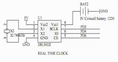
sd card logging
This documentation was compiled as a result of a bee hive temperature monitoring project. Multiple DS18B20 temperature sensors were used to sense the temperature at various locations in the hive. An Arduino with a Nuelectronics sensor shield was used to...
arduino circuit
This page is browser-friendly. To enhance readability, adjust your browser window to be narrower than the full screen. The page consists of two parts: the first part features a basic program demonstrating the RFID reader's functionality, while the second part...
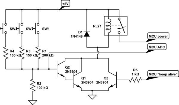
arduino Switch transistor with a low voltage and current
A circuit is being designed that utilizes a combination of switches and resistors to enable a microcontroller to identify which switch has been pressed based on the voltage read, and subsequently perform a switch-specific action. The proposed design incorporates a...