


SINGLE CHIP DIGITAL VOLTMETER
#voltmeter
#A/D converter
#LCD driver
#voltage reference
#continuity testing
#Maxim ICL7129ACPL
#ICL8069
#digital measurement
#precision
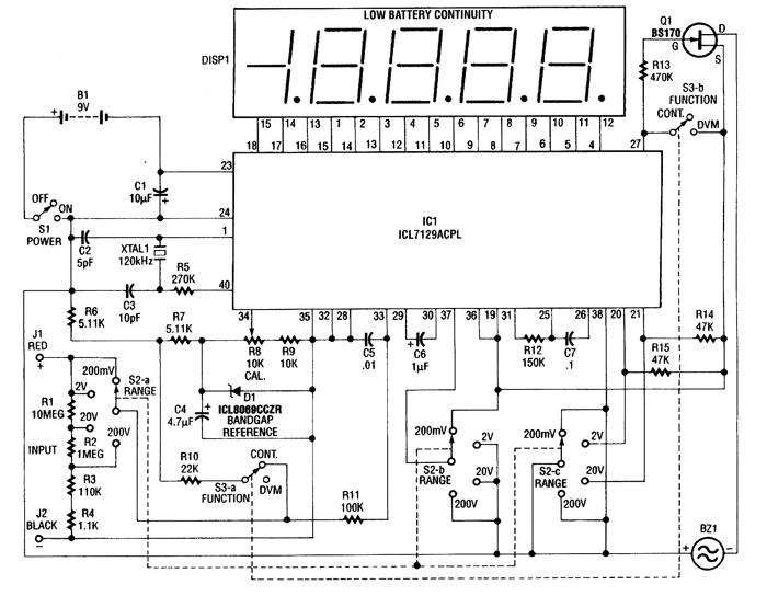
Description: This 4.5-digit digital voltmeter (DVM) circuit is designed around the Maxim ICL7129ACPL analog-to-digital converter (A/D converter) and an LCD driver. It utilizes an ICL8069 CCZR 1.2-V band-gap reference diode for voltage referencing. The switch S2a-b-c allows the selection of one of four voltage ranges, with a maximum limit of 200 V. Additionally, the meter is equipped with a piezoelectric buzzer for continuity testing, and switch S3 is used to toggle between DVM and continuity modes. Crystal 1 can be replaced with a 100 kHz crystal to achieve maximum rejection of 50 Hz, although the standard crystal provides a frequency of 120 kHz for optimal 60 Hz rejection. This performance is attributed to the dual-slope conversion technique implemented in the integrated circuit IC1.
The 4.5-digit DVM circuit operates through a combination of several key components, each fulfilling a specific role in the measurement process. The Maxim ICL7129ACPL serves as the core component, functioning as both the A/D converter and the LCD driver. This integrated circuit is capable of converting analog voltage signals into a digital format, which is then displayed on an LCD screen for user readability.
The ICL8069 CCZR band-gap reference diode is critical for providing a stable reference voltage of 1.2 V, ensuring that the voltage measurements are accurate and consistent across various environmental conditions. The inclusion of switch S2a-b-c allows users to select between four predefined voltage ranges, facilitating measurements up to a maximum of 200 V. This versatility is essential for applications that require different voltage levels to be monitored.
For continuity testing, the circuit incorporates a piezoelectric buzzer that emits sound when a conductive path is detected, aiding in troubleshooting and circuit verification. The functionality of the DVM and continuity testing is managed through switch S3, which allows users to easily switch between modes based on their measurement needs.
The choice of crystal frequency is also significant in this design. The standard crystal operates at 120 kHz, which is optimized for the rejection of 60 Hz noise, a common interference frequency in electrical systems. Alternatively, replacing the crystal with a 100 kHz variant enhances the rejection of 50 Hz noise, making the circuit adaptable to different power line frequencies depending on the region of use. The dual-slope conversion technique utilized in the ICL7129ACPL further enhances measurement accuracy by averaging out noise, resulting in precise and reliable readings. This method is particularly effective in environments with fluctuating electrical signals, ensuring that the DVM provides stable output.
In summary, this DVM circuit is a sophisticated and versatile tool for measuring voltage, equipped with features that enhance its usability and accuracy in various applications.This 4 1/2-digit DVM circuit is built around a Maxim ICL7129ACPL A/D converter and LCD driver. An ICL8069 CCZR 1. 2-V band-gap reference diode is used for a voltage reference. S2a-b-c select one of four ranges up to 200 V (maximum). The meter also has a piezoelectric buzzer for continuity testing. S3 selects either DVM or continuity. Crystal 1 can be changed to 100 kHz if maximum rejection of 50 Hz is desired. The crystal normally provides 120 kHz for best 60-Hz rejection. This is caused by the dual-slope conversion technique used in IC1.
The 4.5-digit DVM circuit operates through a combination of several key components, each fulfilling a specific role in the measurement process. The Maxim ICL7129ACPL serves as the core component, functioning as both the A/D converter and the LCD driver. This integrated circuit is capable of converting analog voltage signals into a digital format, which is then displayed on an LCD screen for user readability.
The ICL8069 CCZR band-gap reference diode is critical for providing a stable reference voltage of 1.2 V, ensuring that the voltage measurements are accurate and consistent across various environmental conditions. The inclusion of switch S2a-b-c allows users to select between four predefined voltage ranges, facilitating measurements up to a maximum of 200 V. This versatility is essential for applications that require different voltage levels to be monitored.
For continuity testing, the circuit incorporates a piezoelectric buzzer that emits sound when a conductive path is detected, aiding in troubleshooting and circuit verification. The functionality of the DVM and continuity testing is managed through switch S3, which allows users to easily switch between modes based on their measurement needs.
The choice of crystal frequency is also significant in this design. The standard crystal operates at 120 kHz, which is optimized for the rejection of 60 Hz noise, a common interference frequency in electrical systems. Alternatively, replacing the crystal with a 100 kHz variant enhances the rejection of 50 Hz noise, making the circuit adaptable to different power line frequencies depending on the region of use. The dual-slope conversion technique utilized in the ICL7129ACPL further enhances measurement accuracy by averaging out noise, resulting in precise and reliable readings. This method is particularly effective in environments with fluctuating electrical signals, ensuring that the DVM provides stable output.
In summary, this DVM circuit is a sophisticated and versatile tool for measuring voltage, equipped with features that enhance its usability and accuracy in various applications.This 4 1/2-digit DVM circuit is built around a Maxim ICL7129ACPL A/D converter and LCD driver. An ICL8069 CCZR 1. 2-V band-gap reference diode is used for a voltage reference. S2a-b-c select one of four ranges up to 200 V (maximum). The meter also has a piezoelectric buzzer for continuity testing. S3 selects either DVM or continuity. Crystal 1 can be changed to 100 kHz if maximum rejection of 50 Hz is desired. The crystal normally provides 120 kHz for best 60-Hz rejection. This is caused by the dual-slope conversion technique used in IC1.
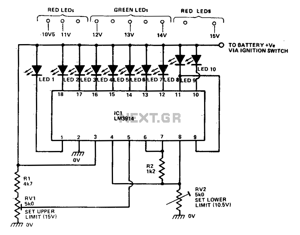
Bargrapk car voltmeter
The LM39X4 functions as a LED-driving voltmeter, with its maximum and minimum readings determined by the resistor values R2 and RV2. When properly calibrated, the device operates within a 2-volt to 3-volt range but is designed to read supply voltages...
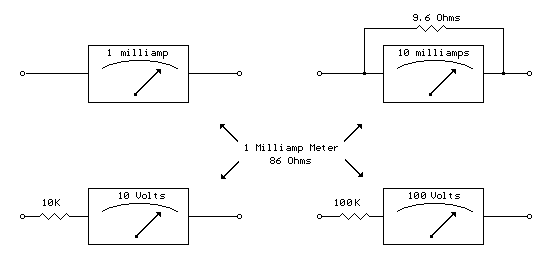
Analog Milliamp Meter Used as Voltmeter circuit
A milliamp meter can function as a voltmeter by incorporating a series resistance. The required resistance is calculated by dividing the full-scale voltage reading by the full-scale current of the meter movement. For instance, using a 1 milliamp meter to...
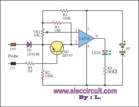
Very simple voltmeter with ic741
This circuit is capable of measuring voltages up to 15 volts, utilizing a 9-volt battery that draws a current of only 23 mA. The input circuit includes a diode for protection.
The circuit design features a voltage measurement system that is...
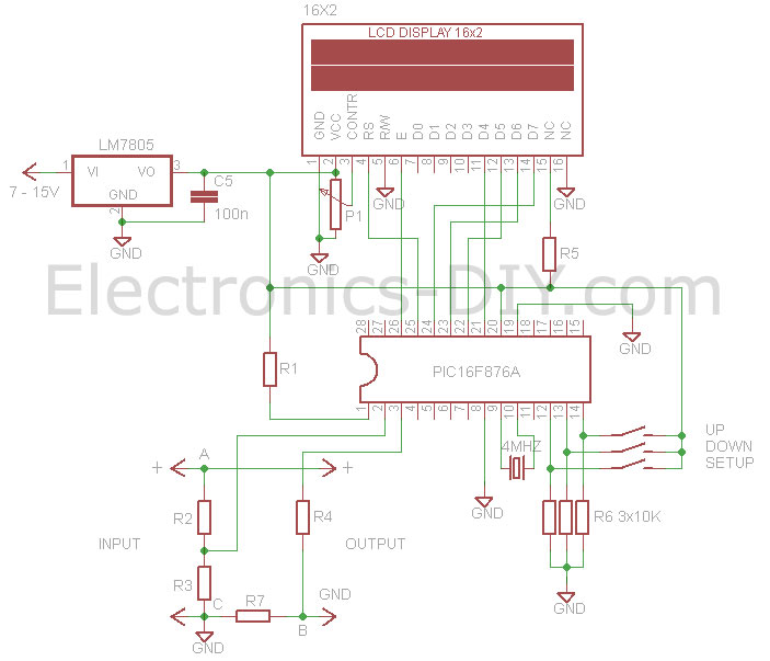
Voltmeter Ammeter
This voltmeter ammeter is designed to measure output voltage ranging from 0-70V to 0-500V with a resolution of 100mV and can measure current from 0-10A or more with a resolution of 10mA. It is an ideal addition to any DIY...
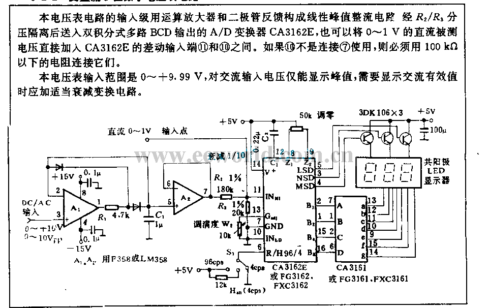
AC/DC 3 digits voltmeter circuit
The input stage of this voltmeter circuit utilizes an operational amplifier and diode feedback to create a linear peak value rectifier circuit. A partial pressure isolation through resistors R1 and R2 directs the signal to a dual multi-channel BCD output...
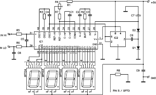
ICL7107 Digital LED Voltmeter
This circuit is a digital voltmeter with an LED display, ideal for measuring the output voltage of a DC power supply. It features a 3.5-digit LED display with a negative voltage indicator and measures DC voltages from 0 to 199.9V...
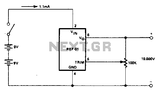
Precision calibration standard
An external power supply that provides a voltage higher than the maximum expected rating of the zener diodes to be tested is required. Potentiometer RV1 is adjusted until the meter reading stabilizes. This reading represents the breakdown voltage of the...
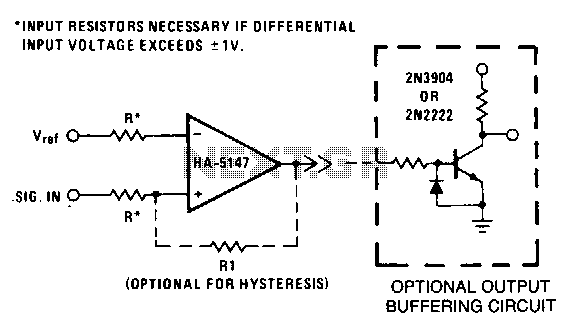
Precision-threshold-detector
This circuit requires low noise, stable offset voltages, high open-loop gain, and high speed. These requirements are fulfilled by the HA5147. Standard variations of this circuit can be easily implemented using the HA-5147. For instance, hysteresis can be introduced by...
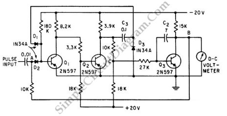
Peak (Pulse) Voltmeter
This is a Peak Voltmeter circuit. This circuit can be viewed as a pulse stretcher, which captures fast pulse signals to be measured by a slow response voltmeter.
The Peak Voltmeter circuit is designed to accurately measure the peak voltage of...