


Speed Pulse Generator For PC Fans
#PC fan
#speed pulse
#voltage spikes
#signal generation
#tachometer
#fan control
#pulse generator
#monitoring
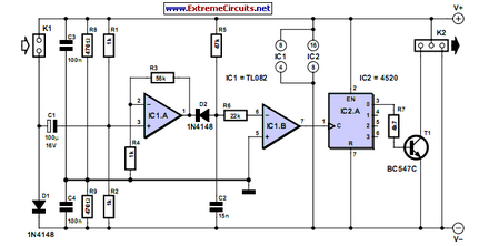
Description: This circuit generates speed pulses from the speed-dependent voltage spikes produced by commonly used types of PC power supply fans, which are superimposed.
The circuit utilizes the voltage spikes generated by the fan's operation to create a series of speed pulses that can be used for various monitoring and control applications. Typically, the fan operates at varying speeds based on temperature and system load, which results in corresponding voltage changes. These voltage spikes can be captured and processed to derive a pulse signal that reflects the fan's speed.
The circuit design may include components such as a diode to rectify the AC voltage spikes, a capacitor to smooth the output, and a comparator to convert the analog signal into a digital pulse. This digital pulse can then be fed into a microcontroller or a digital signal processor for further analysis or control actions.
The output frequency of the generated pulses is directly proportional to the fan speed, allowing for real-time monitoring of the fan's operational status. This information can be utilized in thermal management systems to ensure optimal performance and prevent overheating in electronic devices. Additionally, the circuit can be integrated into larger systems for feedback mechanisms, enhancing the overall efficiency of the cooling solutions employed in PC power supplies.This circuit generates speed pulses from the speed-dependent voltage spikes generated by commonly used types of PC power supply fans, which are superimpos..
The circuit utilizes the voltage spikes generated by the fan's operation to create a series of speed pulses that can be used for various monitoring and control applications. Typically, the fan operates at varying speeds based on temperature and system load, which results in corresponding voltage changes. These voltage spikes can be captured and processed to derive a pulse signal that reflects the fan's speed.
The circuit design may include components such as a diode to rectify the AC voltage spikes, a capacitor to smooth the output, and a comparator to convert the analog signal into a digital pulse. This digital pulse can then be fed into a microcontroller or a digital signal processor for further analysis or control actions.
The output frequency of the generated pulses is directly proportional to the fan speed, allowing for real-time monitoring of the fan's operational status. This information can be utilized in thermal management systems to ensure optimal performance and prevent overheating in electronic devices. Additionally, the circuit can be integrated into larger systems for feedback mechanisms, enhancing the overall efficiency of the cooling solutions employed in PC power supplies.This circuit generates speed pulses from the speed-dependent voltage spikes generated by commonly used types of PC power supply fans, which are superimpos..
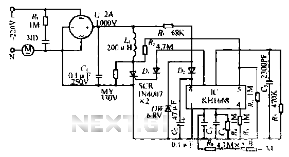
Touch a fan speed control circuit
The synchronous vibration circuit operates with a control logic that includes three primary components. An internal oscillator is initiated by a synchronization pulse, transitioning to a low state immediately after the pulse. Upon power activation, the internal circuitry undergoes an...
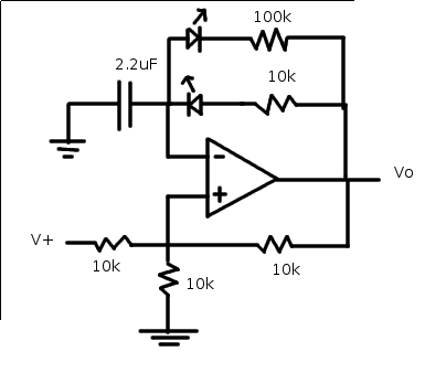
pulse generator circuit
The relaxation oscillator generates a relatively consistent square wave. By altering the duty cycle, the effect can be visualized using LEDs. The following variation of the relaxation oscillator circuit can be assembled.
The relaxation oscillator circuit typically consists of a resistor,...
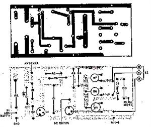
tachometer circuit diagram
The system primarily consists of a permanent magnet disk, an integrated Hall sensor, a strobe gate, time base signal circuits, a power counting circuit, and a digital display circuit. The counting and digital display circuit utilizes the CMOS-LED digital display...
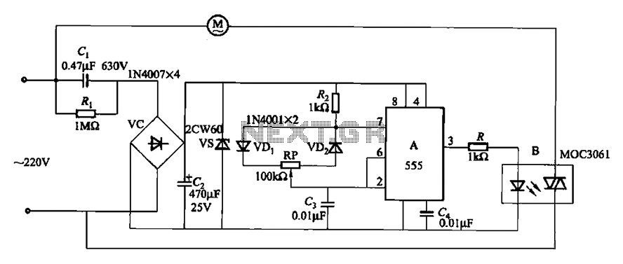
Fans of natural wind simulator circuit 2
The circuit depicted in Figure 3-9 shares similarities with Figure 3-8, with the distinction that the zero-off MOC3061 type photoelectric coupler is directly connected to control the operation of the fan.
The circuit utilizes the MOC3061, a phototransistor optoisolator, which serves...
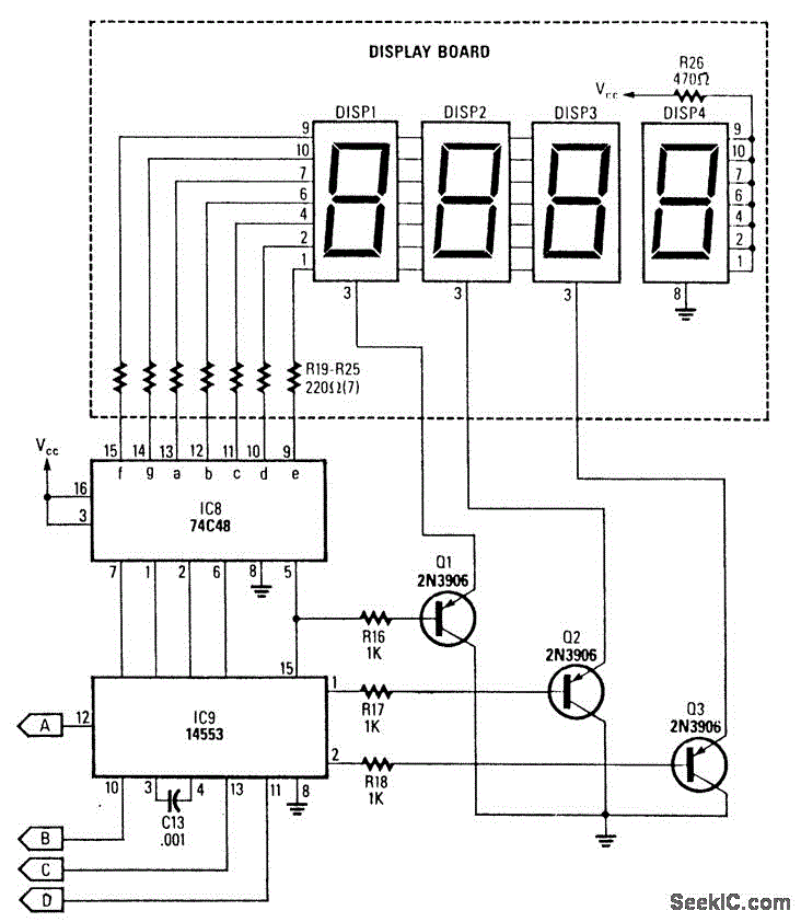
DIGITAL TACHOMETER COUNTER
This circuit generates a readout for a digital tachometer. IC9 functions as a 3-digit LED display driver, counter, and latch. IC8 operates the common cathode LEDs, which are activated by transistors Q1, Q2, and Q3. Refer to page 268, Fig....
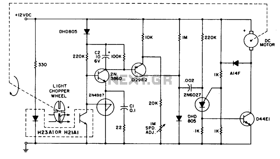
Tachometer feedback control
The system employs the H21A1 optocoupler and a chopper disc to achieve enhanced speed regulation. This is effective when the dynamic characteristics of both the motor system and the feedback system are appropriately matched, ensuring stability. The tachometer feedback system...
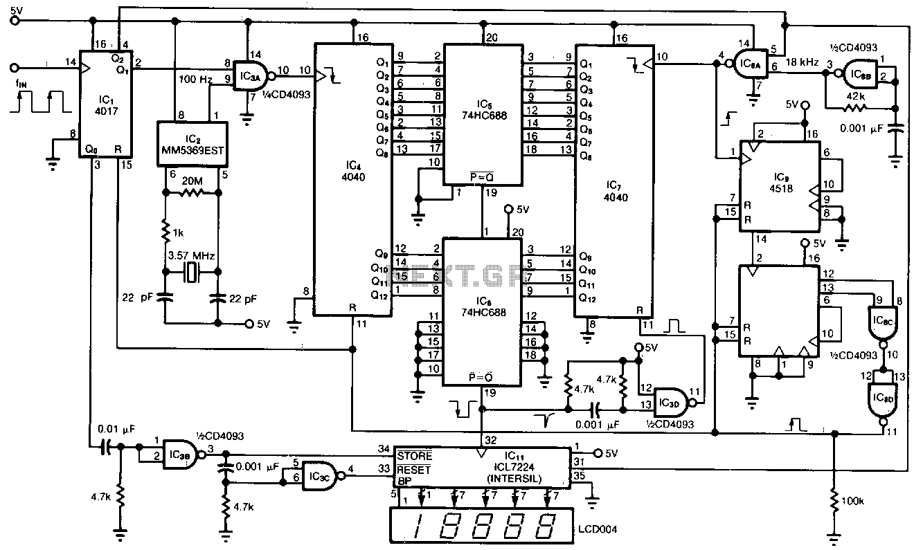
Low-frequency-tachometer
This tachometer allows for the measurement of heartbeats, respiratory rates, and other low-frequency events that occur at intervals ranging from 0.33 to 40.96 seconds. The circuit detects the frequency, calculates the corresponding pulses per minute, and updates the LCD display...
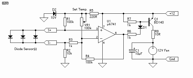
Motor Fan heat controller
The controller uses one or more ordinary silicon diodes as a sensor, and uses a cheap opamp as the amplifier. I designed this circuit to use 12V computer fans, as these are now very easy to get cheaply. These fans...
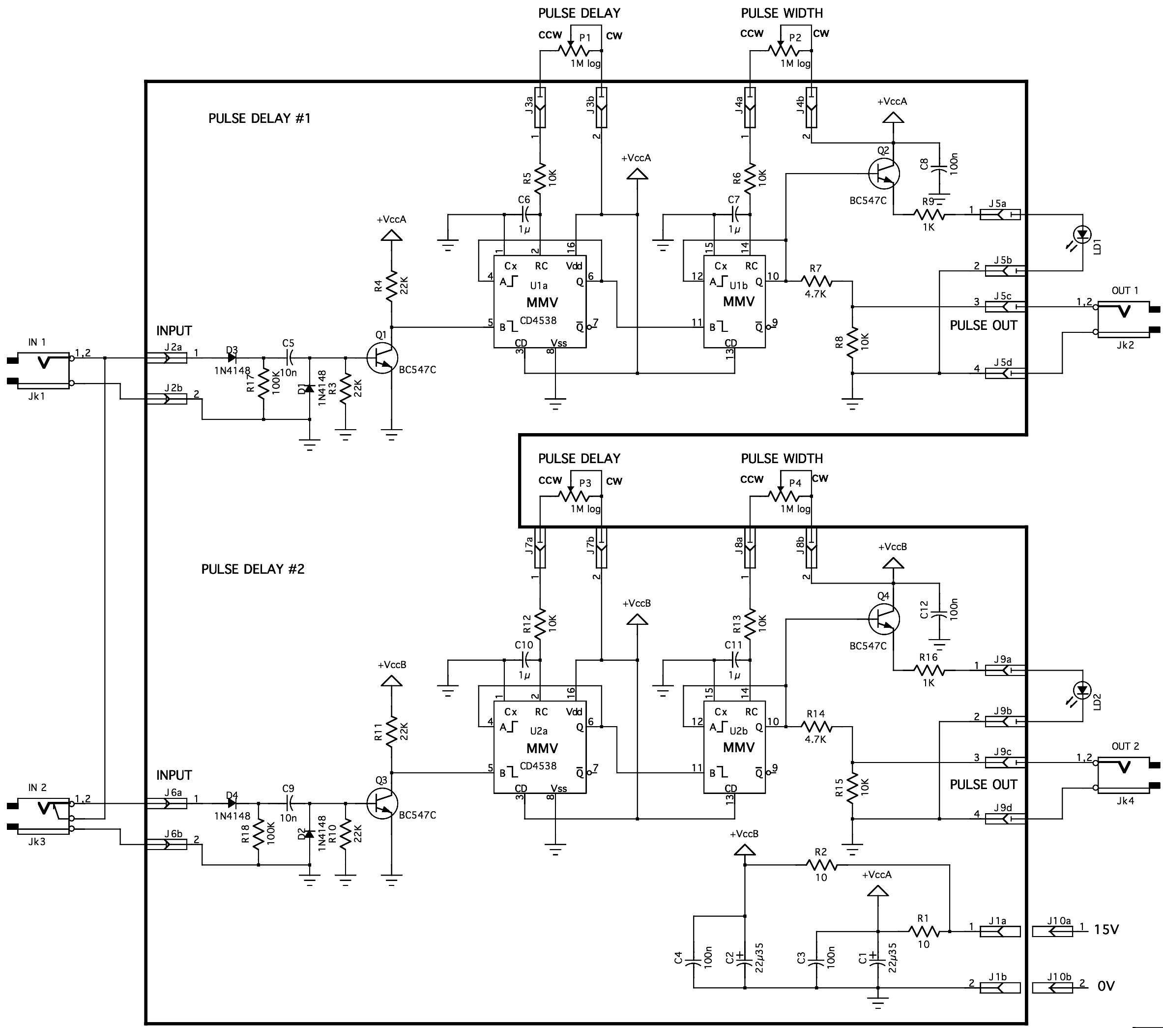
PULSE DELAY
When a GATE signal (between 3V and 15V) is applied, the capacitor C5 functions as a differentiator, converting the gate signal into a brief positive pulse with a width of 10 ms. Diode D1 protects the circuit from negative voltages....