


SWR Meter
#SWR meter
#radio frequency
#forward power
#reverse power
#RF measurement
#antenna
#ham radio
#electronics
#circuit design
#N2PK
Description: Direct-reading SWR meters automatically compute the ratio of forward and reverse powers, eliminating the need for sensitivity adjustments. Several years ago, a meter was built based on a design by G3WPO, which was sold as a kit by Cirkit. While it functioned well, it required periodic adjustments of multiple trimmers to maintain accuracy. A more modern design by N2PK was later discovered. This design utilizes a pair of AD8307 RSSI (Received Signal Strength Indicator) chips to generate DC voltages proportional to the logarithm of forward and reflected power levels. These DC voltages can be subtracted using an operational amplifier to yield a voltage proportional to SWR, which remains largely independent of power levels. The forward DC voltage also drives a separate power meter. Modifications were made to incorporate a "Stockton" directional coupler and to enable peak-reading capabilities. The meter provides an accurate SWR readout for any power level between 10mW and 1000W. The power meter is designed to measure from 100mW to 1000W, with options to adjust the circuit for different upper and lower power limits within the range of 100µW to 1000W. The circuit diagram is available for reference. The coupler's design is crucial for the unit's accuracy, and it was built as a separate unit to isolate strong RF fields from the processing circuitry. Forward and reflected RF samples are transmitted via RG174 coax cable to the processing unit. The accuracy of the coupler supplied by N8LP as part of the LP100 kit was highly regarded, prompting the use of the same design for this meter. A 6dB pad in the coupler and an 11.2dB pad at the processing unit's input ensure isolation for the interconnecting cables.
The described SWR meter is a sophisticated device that facilitates direct measurement of standing wave ratio (SWR) without manual adjustments, making it user-friendly and efficient. The core of the system is the utilization of two AD8307 RSSI chips, which are integral in converting RF signals into DC voltages. These chips operate on the principle of logarithmic amplification, allowing for a wide dynamic range and enabling accurate readings across varying power levels.
The operational amplifier's role in the circuit is to perform a differential measurement of the forward and reflected voltages, which directly correlates to the SWR value. This method enhances the accuracy and reliability of the readings, as the output is less susceptible to variations in the input power levels. The incorporation of a directional coupler, specifically the "Stockton" design, is critical as it ensures that the RF samples are taken with minimal loss and distortion, thereby preserving the integrity of the measurements.
The choice of RG174 coaxial cable for transmitting RF samples to the processing unit is also significant. This type of cable is known for its low-loss characteristics at RF frequencies, ensuring that the signals remain strong and clear throughout the measurement process. The inclusion of attenuation pads in both the coupler and processing unit serves a dual purpose: it protects the sensitive components from high power levels and minimizes reflections that could lead to inaccurate readings.
The meter's design allows for flexibility in power measurement, enabling it to accommodate a wide range of applications, from low-power experiments to high-power transmissions. The ability to modify the circuit for different power limits adds to its versatility, making it suitable for various environments and user needs. Overall, the meticulous design and thoughtful component selection contribute to a robust and precise SWR meter, ideal for amateur and professional radio operators alike.Direct-reading" SWR meters that automatically compute the ratio of Forward and Reverse powers (i. e. you don`t have to adjust any sensitivity controls). Several years ago I built one to a design by G3WPO that was sold as a kit by Cirkit. It worked quite well, but it contained numerous trimmers that needed adjusting from time to time to maintain the accuracy. Then I discovered a much more modern design by N2PK. Paul uses a pair of AD8307 RSSI (Received Signal Strength Indicator) chips to produce DC voltages that are proportional to the logarithm of the Forward and Reflected power levels. These DC voltages can then be subtracted in an Op Amp to produce a voltage proportional to SWR which is essentially independent of power level.
The Forward DC voltage also drives a separate Power meter. I have modified Paul`s design to use a "Stockton" directional coupler, and to provide a peak-reading capability. The meter automatically provides an accurate readout of SWR for any power level between 10mW and 1000W.
I arranged for the Power meter to cover the range 100mW to 1000W, but it is easy to change the circuit to set upper and lower power limits to any values in the range 100uW to 1000W. You can see the circuit diagram here. The design of the coupler is critical to the accuracy of the unit. I chose to build the coupler as a separate unit so that strong RF fields could be kept away from the processing circuitry.
The Forward and Reflected RF samples are fed via RG174 coax cable to the "processing" unit. I had been very impressed with the accuracy of the coupler supplied by N8LP as part of his LP100 kit, so I used the same design for my meter. A 6dB pad in the coupler, and a 11. 2dB pad at the input to the processing unit provide isolation for the interconnecting cables.
The described SWR meter is a sophisticated device that facilitates direct measurement of standing wave ratio (SWR) without manual adjustments, making it user-friendly and efficient. The core of the system is the utilization of two AD8307 RSSI chips, which are integral in converting RF signals into DC voltages. These chips operate on the principle of logarithmic amplification, allowing for a wide dynamic range and enabling accurate readings across varying power levels.
The operational amplifier's role in the circuit is to perform a differential measurement of the forward and reflected voltages, which directly correlates to the SWR value. This method enhances the accuracy and reliability of the readings, as the output is less susceptible to variations in the input power levels. The incorporation of a directional coupler, specifically the "Stockton" design, is critical as it ensures that the RF samples are taken with minimal loss and distortion, thereby preserving the integrity of the measurements.
The choice of RG174 coaxial cable for transmitting RF samples to the processing unit is also significant. This type of cable is known for its low-loss characteristics at RF frequencies, ensuring that the signals remain strong and clear throughout the measurement process. The inclusion of attenuation pads in both the coupler and processing unit serves a dual purpose: it protects the sensitive components from high power levels and minimizes reflections that could lead to inaccurate readings.
The meter's design allows for flexibility in power measurement, enabling it to accommodate a wide range of applications, from low-power experiments to high-power transmissions. The ability to modify the circuit for different power limits adds to its versatility, making it suitable for various environments and user needs. Overall, the meticulous design and thoughtful component selection contribute to a robust and precise SWR meter, ideal for amateur and professional radio operators alike.Direct-reading" SWR meters that automatically compute the ratio of Forward and Reverse powers (i. e. you don`t have to adjust any sensitivity controls). Several years ago I built one to a design by G3WPO that was sold as a kit by Cirkit. It worked quite well, but it contained numerous trimmers that needed adjusting from time to time to maintain the accuracy. Then I discovered a much more modern design by N2PK. Paul uses a pair of AD8307 RSSI (Received Signal Strength Indicator) chips to produce DC voltages that are proportional to the logarithm of the Forward and Reflected power levels. These DC voltages can then be subtracted in an Op Amp to produce a voltage proportional to SWR which is essentially independent of power level.
The Forward DC voltage also drives a separate Power meter. I have modified Paul`s design to use a "Stockton" directional coupler, and to provide a peak-reading capability. The meter automatically provides an accurate readout of SWR for any power level between 10mW and 1000W.
I arranged for the Power meter to cover the range 100mW to 1000W, but it is easy to change the circuit to set upper and lower power limits to any values in the range 100uW to 1000W. You can see the circuit diagram here. The design of the coupler is critical to the accuracy of the unit. I chose to build the coupler as a separate unit so that strong RF fields could be kept away from the processing circuitry.
The Forward and Reflected RF samples are fed via RG174 coax cable to the "processing" unit. I had been very impressed with the accuracy of the coupler supplied by N8LP as part of his LP100 kit, so I used the same design for my meter. A 6dB pad in the coupler, and a 11. 2dB pad at the input to the processing unit provide isolation for the interconnecting cables.
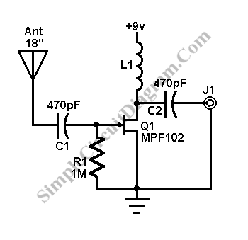
Antenna Booster for FM AM and SW Receiver
This AM/FM antenna booster circuit amplifies the broadband signal from the antenna. This antenna booster is designed to work for FM, AM, and SW receivers.
The AM/FM antenna booster circuit is an essential component for enhancing radio reception across various...
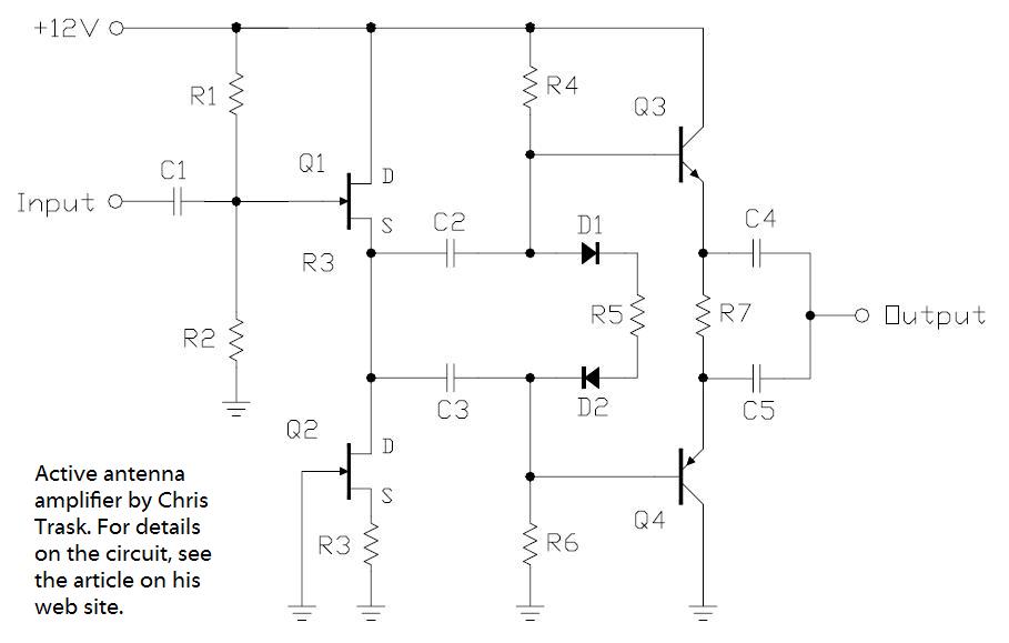
an active whip receiving antenna
In the pursuit of effective small antennas, an active whip antenna was constructed. This compact vertical antenna is linked to a preamplifier, which serves to convert the high impedance of the 50-ohm receiver and coaxial cable. Various designs exist for...
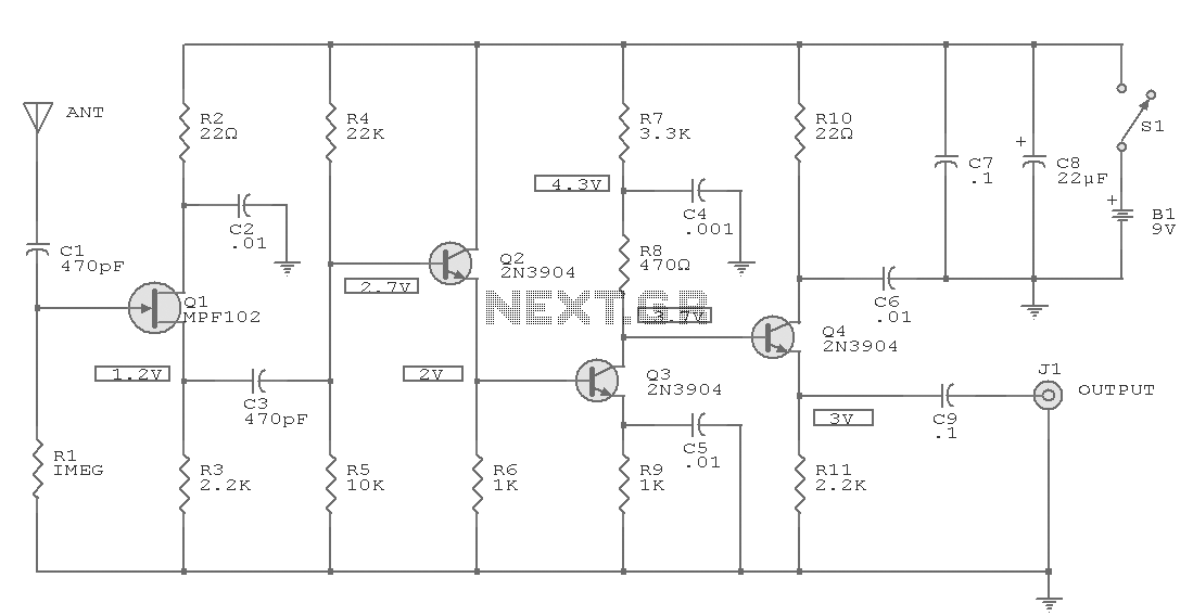
Active Antenna
Antennas that are much shorter than 1/4 wavelength present a very small and highly relative impedance that is dependent on the received frequency. It is difficult to match impedances over a decade of frequency coverage. Instead, input stage Q1 is...
Q- Multiplying Loop Antenna
This circuit is designed to be used in conjunction with the standard 4 foot square loop used in MW for long distance reception.
The described circuit is intended for use with a standard 4-foot square loop antenna, optimized for medium wave...
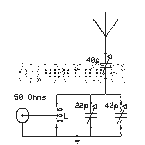
Antenna tunning circuit for 27MHz CB band
The antenna tuning circuit can accommodate 1/2 wave length antennas or higher, for input resistances of 50 Ohms which make it suitable for CB (Citizen Band) transceivers. C1 is for fine tuning and C2 is just for tuning. Turning C3...
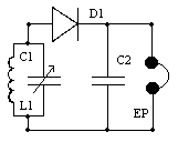
HAM Modulation Monitor
Modulation Monitor is a simple and useful circuit for hams. You can listen to on air transmission from your rig and be sure about the quality of the transmission. It requires no direct connection with the transmitter. In the prototype,...
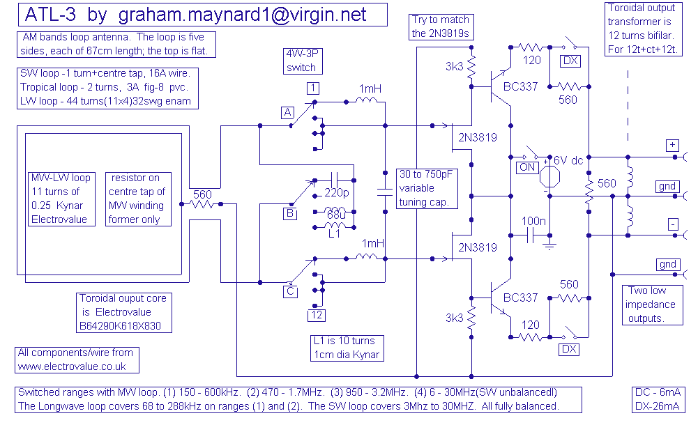
ATL-3 Loop Antenna
This antenna is the result of long term development and user feedback. All ATL-3 loop windings are centre tapped and balanced w.r.t. their amplifier/receiver chassis ground, and therefore electric field interference pick up tends to self cancel. Magnetic noise fields,...
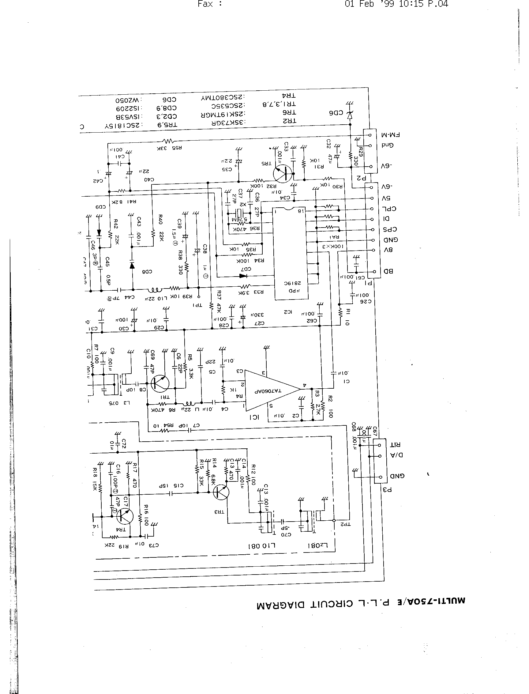
Mic wiring Servicing and alignment
The FDK Multi-750e was introduced in the UK in 1981. This 2-meter ham radio multimode transceiver is offered at an attractive price and includes a matching 70cm transverter that can be controlled directly from the front panel. While many units...
Four Foot Box Loop Antenna
Please find attached your copy of my four foot unamplified box loop. It will tune from 525 kHz to about 1710 kHz covering the entire Broadcast Band. The umbrella stand described in the article is the type you would use...