


Temperature Logger and Standalone Voltage Logger
#temperature logger
#voltage logger
#MOSFET
#data logging
#sensor
#jumper
#standalone
#voltage sensing
#power saving
#circuit modification
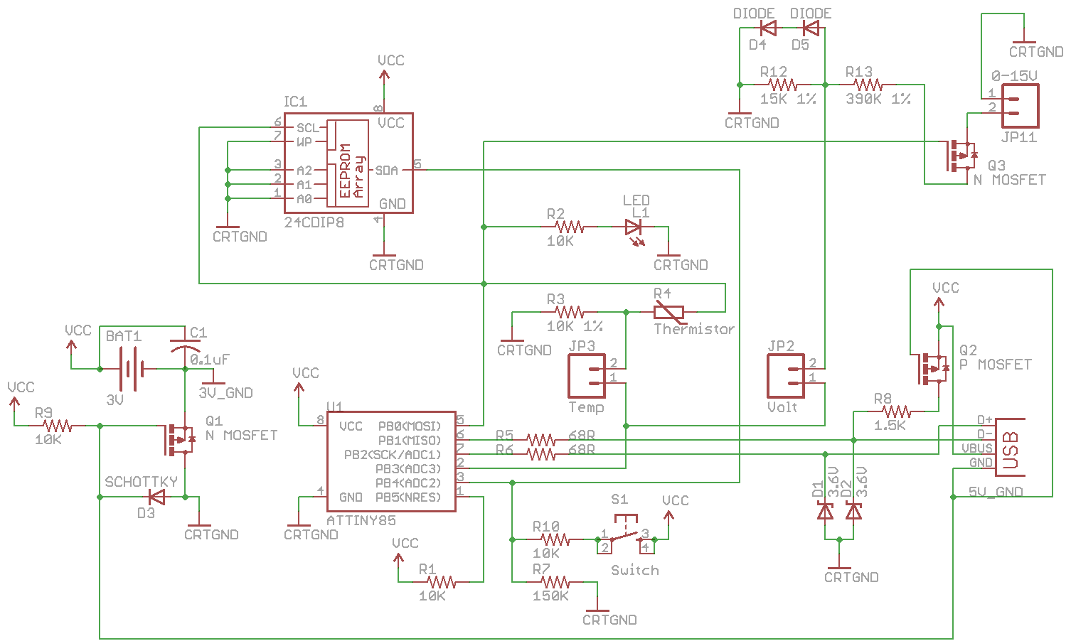
Description: Combine the SATL and SAVL together. The schematic was updated with the voltage sensing circuit. A MOSFET was added to draw power from the voltage source only when needed. There are two jumpers, Temp and Volt, allowing the user to switch between logging temperature and voltage by completing the connection of the jumper and modifying a variable with button presses. The EEPROM is written to based on the current function in use. If the function in use is temperature, data is logged if the data count is less than or equal to the EEPROM memory size. If voltage is logged, data is recorded if the data count is less than or equal to the EEPROM memory size minus one. A new variable, functionInuse, allows the selection between temperature or voltage logging. When the button is held down, the system enters a sleep mode until the button is released. If the button is held for three seconds, the delay time is changed. The user can switch between temperature and voltage logging, and the relevant function is configured. The temperature calculation uses a formula based on a 1024-bit resolution and a 165-degree temperature range. The voltage logging formula calculates the maximum voltage of 15V, yielding a specific byte value. The SATVL_v1.0_Source can be downloaded for use with the v1.0 PCB, and the current program size is 8028 bytes, which is close to the ATtiny85 program size limit.
The combined SATL and SAVL circuit schematic integrates a voltage sensing circuit with a MOSFET to optimize power consumption. The MOSFET acts as a switch, allowing power to be drawn from the voltage source only when necessary, enhancing the overall efficiency of the design. The inclusion of two jumpers, Temp and Volt, provides flexibility in operation, enabling the user to select between temperature and voltage logging by completing the jumper connections. This selection is managed through a variable that can be modified via button presses.
Data logging is managed through an EEPROM interface. The system checks the function in use to determine how data should be recorded. For temperature logging, data is stored if the count does not exceed the defined EEPROM memory size. In contrast, for voltage logging, the data count must remain within the limit of the EEPROM size minus one, ensuring that the logging process does not overflow the memory.
The implementation of a new variable, functionInuse, allows for dynamic switching between the two logging modes. When the button is pressed, the system enters a low-power sleep mode, activating the watchdog timer. If the button remains pressed for three seconds, the delay time for logging is adjusted, enabling further user control over the logging process. The circuit uses interrupt handling to manage button presses efficiently, ensuring that the transition between logging modes occurs without significant delay.
Temperature calculations utilize a formula derived from the system's resolution and temperature range. Specifically, the formula accounts for a 1024-bit resolution across a 165-degree range, resulting in a scaling factor. The final temperature value is calculated by adjusting a baseline value to account for the sensor's characteristics. For voltage logging, a similar approach is taken, where the maximum measurable voltage is factored into the formula to yield a corresponding byte value.
The design is compatible with the SATVL_v1.0_Source, which is intended for use with the forthcoming v1.0 PCB. The program's current size, at 8028 bytes, is approaching the maximum capacity of the ATtiny85 microcontroller, necessitating careful management of code efficiency and memory usage to ensure optimal performance.Combine the SATL and SAVL together. The schematic was updated with the voltage sensing circuit, I added in a Mosfet so that we only draw power from the voltage source when needed and you`ll notice there are 2 jumpersTemp and Volt. You can switch between logging temperature and voltage by completing the connection of the jumper and modifying a variable
with button presses. // Write to EEPROM if (functionInuse = functionTemperature) { if (dataCount <= eepromMap[eepromMemsize]) {. } } else { if (dataCount <= eepromMap[eepromMemsize] - 1) {. } } I`ll spare you most of the modified code as it just has some if statements as above. There is a new variable called functionInuse which lets us choose between temperature or voltage logging. // Button held down if (buttonPressed = 1) { setup_watchdog(T2S); system_sleep(); if (buttonPressed != 1) { // If button is released after 3 seconds, change delay time.
} else { // Change between temperature or voltage logging cbi(GIMSK, PCIE); functionSelect = CONFIGFUNCTION; functionInuse = -1; blinkLed(1, T4S, SKIPLEDOFFDELAY); sbi(GIMSK, PCIE); } } As we did last week, we can calculate the formula which we need to use, 1024 bit / 165 temperature range gives us 6. 206 then we do -40C x 6. 206 gives us our value to minus as 248. The formula is temperature = (value 249) / 6. 206. With voltage logging our maximum voltage is 15V which is a value of 517. All we need to do is divide 517 by 254 for a 1 byte value which gives 2. 035. The formula is voltage = (value 1) * 2. 035) * 0. 001074) * 27. You can download the SATVL_v1. 0_Source which should be used once the v1. 0 PCB is released. At the moment the program size is up to 8028 bytes which is very close to the ATtiny85 program size limit!
The combined SATL and SAVL circuit schematic integrates a voltage sensing circuit with a MOSFET to optimize power consumption. The MOSFET acts as a switch, allowing power to be drawn from the voltage source only when necessary, enhancing the overall efficiency of the design. The inclusion of two jumpers, Temp and Volt, provides flexibility in operation, enabling the user to select between temperature and voltage logging by completing the jumper connections. This selection is managed through a variable that can be modified via button presses.
Data logging is managed through an EEPROM interface. The system checks the function in use to determine how data should be recorded. For temperature logging, data is stored if the count does not exceed the defined EEPROM memory size. In contrast, for voltage logging, the data count must remain within the limit of the EEPROM size minus one, ensuring that the logging process does not overflow the memory.
The implementation of a new variable, functionInuse, allows for dynamic switching between the two logging modes. When the button is pressed, the system enters a low-power sleep mode, activating the watchdog timer. If the button remains pressed for three seconds, the delay time for logging is adjusted, enabling further user control over the logging process. The circuit uses interrupt handling to manage button presses efficiently, ensuring that the transition between logging modes occurs without significant delay.
Temperature calculations utilize a formula derived from the system's resolution and temperature range. Specifically, the formula accounts for a 1024-bit resolution across a 165-degree range, resulting in a scaling factor. The final temperature value is calculated by adjusting a baseline value to account for the sensor's characteristics. For voltage logging, a similar approach is taken, where the maximum measurable voltage is factored into the formula to yield a corresponding byte value.
The design is compatible with the SATVL_v1.0_Source, which is intended for use with the forthcoming v1.0 PCB. The program's current size, at 8028 bytes, is approaching the maximum capacity of the ATtiny85 microcontroller, necessitating careful management of code efficiency and memory usage to ensure optimal performance.Combine the SATL and SAVL together. The schematic was updated with the voltage sensing circuit, I added in a Mosfet so that we only draw power from the voltage source when needed and you`ll notice there are 2 jumpersTemp and Volt. You can switch between logging temperature and voltage by completing the connection of the jumper and modifying a variable
with button presses. // Write to EEPROM if (functionInuse = functionTemperature) { if (dataCount <= eepromMap[eepromMemsize]) {. } } else { if (dataCount <= eepromMap[eepromMemsize] - 1) {. } } I`ll spare you most of the modified code as it just has some if statements as above. There is a new variable called functionInuse which lets us choose between temperature or voltage logging. // Button held down if (buttonPressed = 1) { setup_watchdog(T2S); system_sleep(); if (buttonPressed != 1) { // If button is released after 3 seconds, change delay time.
} else { // Change between temperature or voltage logging cbi(GIMSK, PCIE); functionSelect = CONFIGFUNCTION; functionInuse = -1; blinkLed(1, T4S, SKIPLEDOFFDELAY); sbi(GIMSK, PCIE); } } As we did last week, we can calculate the formula which we need to use, 1024 bit / 165 temperature range gives us 6. 206 then we do -40C x 6. 206 gives us our value to minus as 248. The formula is temperature = (value 249) / 6. 206. With voltage logging our maximum voltage is 15V which is a value of 517. All we need to do is divide 517 by 254 for a 1 byte value which gives 2. 035. The formula is voltage = (value 1) * 2. 035) * 0. 001074) * 27. You can download the SATVL_v1. 0_Source which should be used once the v1. 0 PCB is released. At the moment the program size is up to 8028 bytes which is very close to the ATtiny85 program size limit!
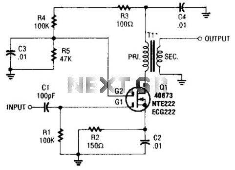
Mosfet Buffer Amplifier Circuit
A MOSFET is utilized as a wideband buffer amplifier. T1 is wound on a toroid of approximately specified diameter, using material suitable for the frequency range, typically between 1 MHz and 20 MHz. The turns ratio should be approximately 4:1,...
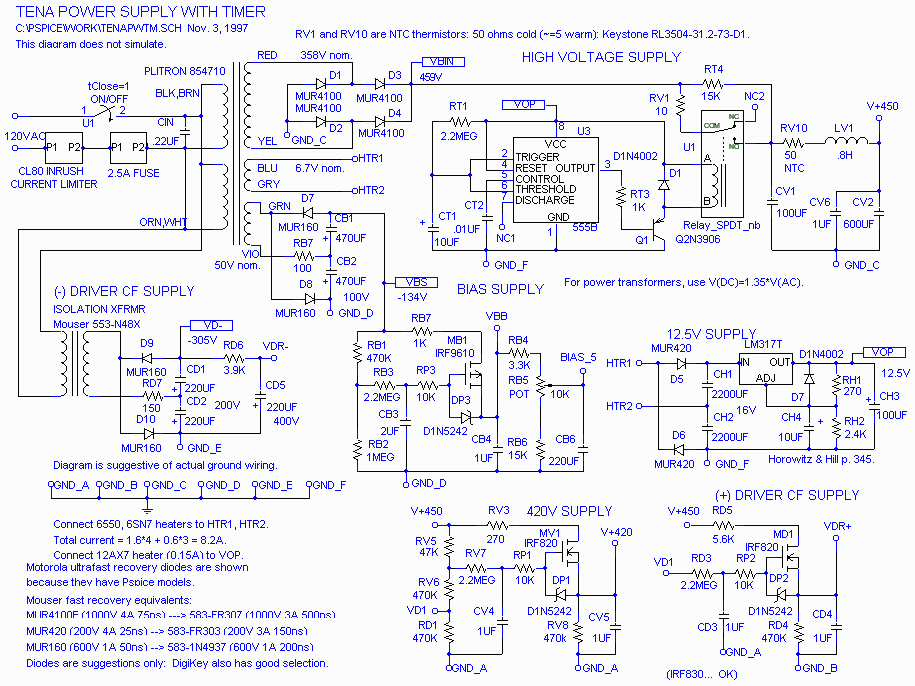
The Emperors New Amplifier
The power supply has been simplified. Power transformers and rectifiers have been omitted, and some components have been removed from the MOSFET voltage regulator circuits: 1N5242 zener diodes between the source and gate and 10k resistors in series with the...
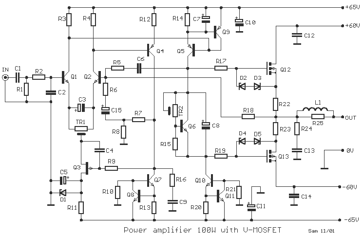
100 Watt MOSFET Power Amplifier
One still designing that it uses in the exit transistor of technology V-mosfet. This transistors to us offer a lot of virtues concerning the simple bipolar transistors, as high speeds, thermic stability, low distortion etc. Beyond this circuit use also...
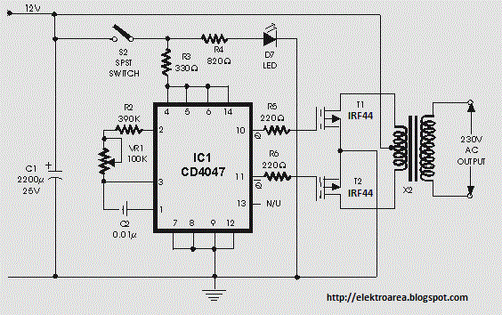
irf44 mosfet based on 100 watt
This inverter circuit can provide a stable 230V output voltage. The operating frequency is determined by a variable resistor (VR1) and is typically set to 60 Hz. Various off-the-shelf transformers can be utilized, or custom-wound transformers can be created for...
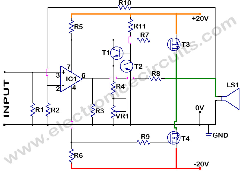
MOSFET Power Amplifier
MOSFET Power Amplifier Circuit diagrams. Two complementary MOSFETs are used to deliver 20W into 8Ω.
The described MOSFET power amplifier circuit utilizes two complementary MOSFETs, which are arranged in a push-pull configuration to efficiently amplify audio signals. The circuit is designed...
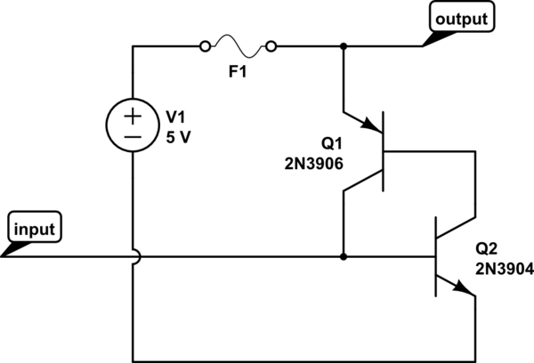
switches Default-on latch-off MOSFET power switch
The circuit should default to the "on" state when first connected. However, if a specific signal goes high for a brief duration (approximately 10 microseconds), the circuit should turn off and remain off. The challenge lies in achieving the "default...
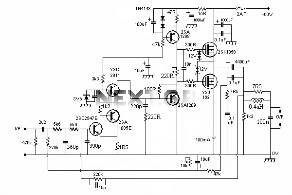
100W Mosfet Power Amplifier
In this circuit we use the 2SK1058 and the 2SJ162 Mosfets. This could be avoided by a fairly simple bootstrapping circuit, but the improvement in maximum output may be just a fraction of a dB, depending on the supply voltage...
60w amplifier mosfet irfp240
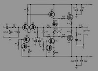
The supply voltage rails were conservatively maintained at +40V and -40V. For those interested in experimentation, the supply voltage can be increased to a maximum of +50V and -50V, enabling the amplifier to reach its target output of 100W into...
Basic mosfet switch question
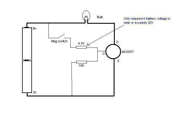
In this schematic provided by Jimmy M, will this circuit drain the batteries when the light is not in use? There is consideration for building a MOSFET circuit to be used in a compact application, where the original bulky switch...