


The electric thermometer circuit composed of LM134
#LM134
#thermometer
#temperature sensor
#voltage output
#current output
#precision
#low voltage
#analog circuit
#sensor circuit
#thermodynamics
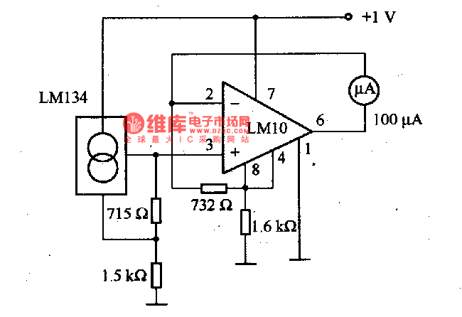
Description: This is an electric thermometer circuit composed of the LM134. In the circuit, the voltage or current output by the LM134 is proportional to the thermodynamic temperature, which can be read on a 100 µA meter. The test temperature range of the meter is from -55°C to 150°C. The power supply can operate even when the voltage is below 1V; however, when precision is required...
The electric thermometer circuit utilizing the LM134 is designed to provide accurate temperature readings across a specified range. The LM134 is a precision current source that converts temperature variations into corresponding output currents. This output is directly proportional to the temperature being measured, allowing for a linear response that is easy to interpret.
The circuit typically includes a temperature sensor, such as a thermistor or a thermocouple, which generates a voltage or current signal based on the ambient temperature. This signal is fed into the LM134, which regulates the output current that corresponds to the sensed temperature. The output current is then directed to a 100 µA analog meter, which displays the temperature in a user-friendly manner.
The operational range of this thermometer is from -55°C to 150°C, making it suitable for a variety of applications, including environmental monitoring and industrial processes. The use of a low-voltage power supply is advantageous, as the circuit can function effectively even when the supply voltage drops below 1V, ensuring reliability in low-power scenarios.
For enhanced precision, additional components such as operational amplifiers or calibration resistors may be integrated into the circuit. These components can help fine-tune the output and compensate for any non-linearities inherent in the temperature sensor or the LM134 itself. Overall, this electric thermometer circuit is a robust solution for accurate temperature measurement in diverse settings.This is the electric thermometer circuit composed of LM134. In the circuit, the voltage or current output by LM134 is in proportion to the thermodynamics temperature, which can be read out on the 100?A meter, the test temperature range of the meter is -55?150?. The power supply can work even when the voltage is under 1V, but when the precision requirement i..
The electric thermometer circuit utilizing the LM134 is designed to provide accurate temperature readings across a specified range. The LM134 is a precision current source that converts temperature variations into corresponding output currents. This output is directly proportional to the temperature being measured, allowing for a linear response that is easy to interpret.
The circuit typically includes a temperature sensor, such as a thermistor or a thermocouple, which generates a voltage or current signal based on the ambient temperature. This signal is fed into the LM134, which regulates the output current that corresponds to the sensed temperature. The output current is then directed to a 100 µA analog meter, which displays the temperature in a user-friendly manner.
The operational range of this thermometer is from -55°C to 150°C, making it suitable for a variety of applications, including environmental monitoring and industrial processes. The use of a low-voltage power supply is advantageous, as the circuit can function effectively even when the supply voltage drops below 1V, ensuring reliability in low-power scenarios.
For enhanced precision, additional components such as operational amplifiers or calibration resistors may be integrated into the circuit. These components can help fine-tune the output and compensate for any non-linearities inherent in the temperature sensor or the LM134 itself. Overall, this electric thermometer circuit is a robust solution for accurate temperature measurement in diverse settings.This is the electric thermometer circuit composed of LM134. In the circuit, the voltage or current output by LM134 is in proportion to the thermodynamics temperature, which can be read out on the 100?A meter, the test temperature range of the meter is -55?150?. The power supply can work even when the voltage is under 1V, but when the precision requirement i..
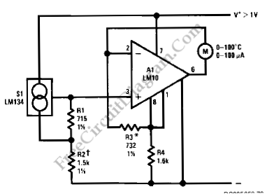
LM134-LM10 Thermometer/Temperature Sensor
Using LM134 and LM10 integrated circuits, a thermometer can be constructed with a sensing range of -55 to 150 °C. The ideal meter for this circuit is a 0-200 µA.
The proposed thermometer circuit utilizes the LM134, a current source IC,...
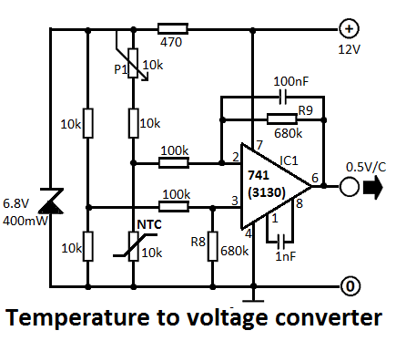
Temperature to Voltage Converter Circuit
This simple temperature-to-voltage converter circuit allows for precise measurement of room temperature using an NTC resistor or thermistor.
The temperature-to-voltage converter circuit typically employs a negative temperature coefficient (NTC) thermistor, which exhibits a decrease in resistance as temperature increases. This property...
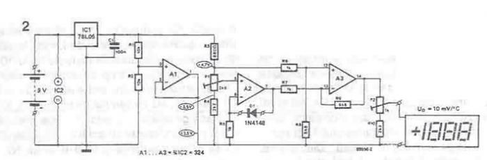
Thermometer circuit schematic using operational amplifiers
A simple thermometer can be constructed using operational amplifiers and a standard or protective diode, such as the 1N4148, as depicted in the electronic diagram below. A constant reference voltage is supplied to the non-inverting input of the operational amplifier....
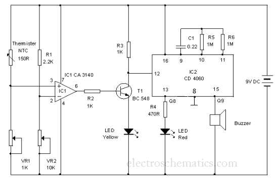
Cold Sensor
The resistance decreases when the temperature in its vicinity increases by one degree or more. Component: LED, Buzzer, Transistor, Capacitor, etc.
The described component exhibits a negative temperature coefficient, which means that its resistance decreases as ambient temperature increases. This behavior...
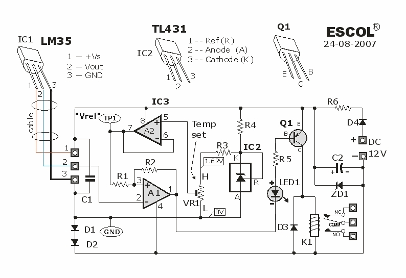
Temperature Controlled Relay Circuit
This temperature-controlled relay circuit is a simple yet highly accurate thermal control circuit that can be used in applications where automatic temperature regulation is required.
The temperature-controlled relay circuit operates by monitoring the ambient temperature using a temperature sensor, such as...
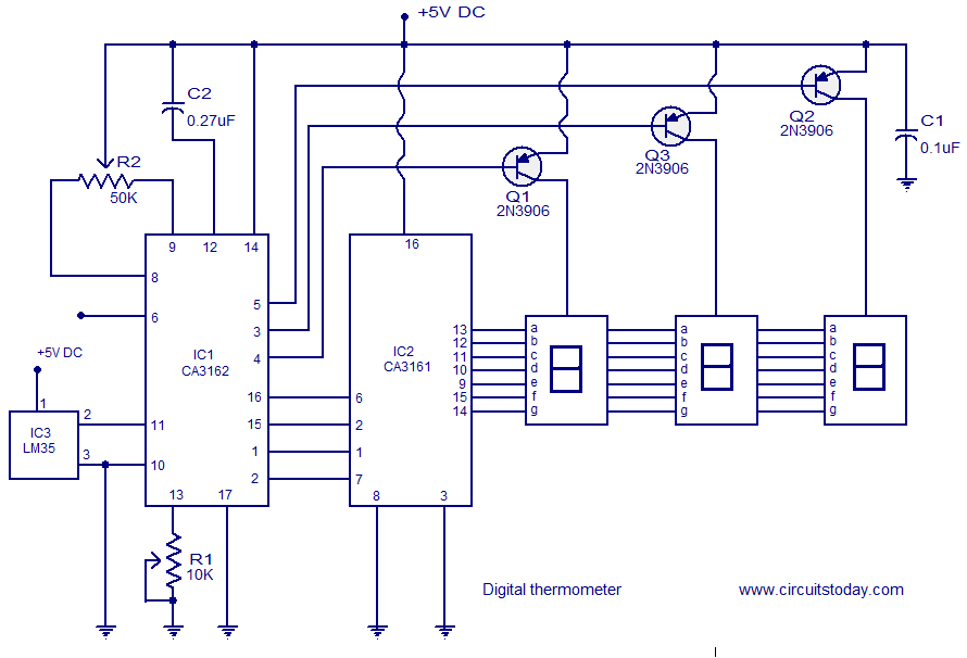
Digital thermometer circuit based on CA3162 CA3162 and LM35
A simple digital thermometer circuit without a microcontroller and featuring a seven-segment LED readout is presented. The circuit utilizes three integrated circuits (ICs): CA3162, CA3161, and LM35. The CA3162 is a monolithic analog-to-digital (A/D) converter with a BCD output. This...
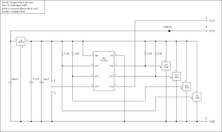
Schematics Serial Temperature Sensor Data Logger
The microcontroller program is designed to support two communication protocols: the one-wire bus utilized by the DS1820 temperature sensor and the serial protocol used for communication with a computer. Upon power-up, the program retrieves data from the temperature sensors and...
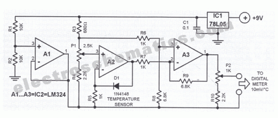
Diode digital thermometer circuit
This digital thermometer circuit diagram utilizes a standard 1N4148 diode as the temperature sensor. The temperature coefficient of the diode is -2 mV/°C.
The digital thermometer circuit leverages the characteristics of the 1N4148 diode, which exhibits a predictable voltage drop that...
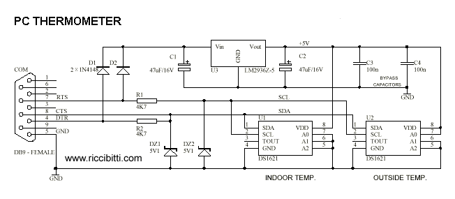
PC-powered thermometer
A real-size printout of the PCB is created to verify the dimensions of all components against it. If a component is too large or small to fit its PCB pads, adjustments to the PCB layout can be made, or a...