


TV Relative Signal Strength Meter PCB
#TV signal
#antenna
#FM detector
#signal strength
#meter
#calibration
#sensitivity control
#portable
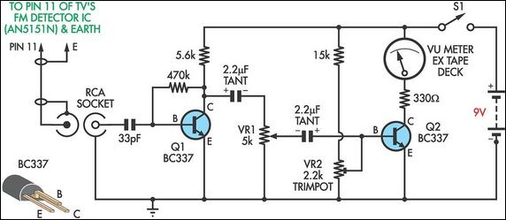
Description: This circuit was designed to assist in the installation of TV antennas. The signal is monitored using a small portable TV set, and this circuit monitors the output of the TV's FM detector IC via a shielded lead. To initially calibrate the meter, trimpot VR2 should be adjusted to zero the meter. Trimpot VR1 serves as a sensitivity control and can be set for a preset reading (i.e., 0 dB) or calibrated in millivolts. Rotating the antenna for a minimum reading on the meter (indicating FM quieting) provides the optimum orientation for the antenna.
The circuit operates by utilizing a small portable TV set to monitor the signal strength received from the antenna. The core component of this setup is the FM detector integrated circuit (IC) within the TV, which converts the RF signals into an audio frequency that can be interpreted by the meter. The output from the FM detector IC is accessed through a shielded lead to minimize interference from external sources, ensuring accurate readings.
Calibration of the circuit is critical for optimal performance. The trimpot VR2 is used to zero the meter, establishing a baseline reference point. This step is essential for ensuring that subsequent readings accurately reflect the signal strength being received. The sensitivity control, trimpot VR1, allows for flexibility in the measurements. It can be adjusted to provide a preset reading of 0 dB or calibrated to display millivolt readings, depending on the user's preference or specific requirements of the installation.
To achieve the best reception, the antenna's orientation must be adjusted based on the readings from the meter. The goal is to find the position that yields the lowest reading on the meter, which indicates FM quieting. This phenomenon occurs when the signal-to-noise ratio is at its highest, resulting in a clearer audio output. By following this procedure, users can effectively optimize the placement of their TV antennas, ensuring the best possible signal reception for their viewing experience.
This circuit design provides a practical solution for installers and users alike, facilitating the installation process and enhancing the overall performance of TV antennas.Circuit This circuit was designed to assist the installation of TV antennas. The signal is monitored using a small portable TV set and this circuit monitors the output of the TV`s FM detector IC via a shielded lead. To initially calibrate the meter, adjust trimpot VR2 to zero the meter. Trimpot VR1 is a sensitivity control and can be set for a pre set reading (ie, 0dB) or can be calibrated in millivolts. Rotating the antenna for a minimum reading on the meter (indicating FM quieting) gives the optimum orientation for the antenna.
The circuit operates by utilizing a small portable TV set to monitor the signal strength received from the antenna. The core component of this setup is the FM detector integrated circuit (IC) within the TV, which converts the RF signals into an audio frequency that can be interpreted by the meter. The output from the FM detector IC is accessed through a shielded lead to minimize interference from external sources, ensuring accurate readings.
Calibration of the circuit is critical for optimal performance. The trimpot VR2 is used to zero the meter, establishing a baseline reference point. This step is essential for ensuring that subsequent readings accurately reflect the signal strength being received. The sensitivity control, trimpot VR1, allows for flexibility in the measurements. It can be adjusted to provide a preset reading of 0 dB or calibrated to display millivolt readings, depending on the user's preference or specific requirements of the installation.
To achieve the best reception, the antenna's orientation must be adjusted based on the readings from the meter. The goal is to find the position that yields the lowest reading on the meter, which indicates FM quieting. This phenomenon occurs when the signal-to-noise ratio is at its highest, resulting in a clearer audio output. By following this procedure, users can effectively optimize the placement of their TV antennas, ensuring the best possible signal reception for their viewing experience.
This circuit design provides a practical solution for installers and users alike, facilitating the installation process and enhancing the overall performance of TV antennas.Circuit This circuit was designed to assist the installation of TV antennas. The signal is monitored using a small portable TV set and this circuit monitors the output of the TV`s FM detector IC via a shielded lead. To initially calibrate the meter, adjust trimpot VR2 to zero the meter. Trimpot VR1 is a sensitivity control and can be set for a pre set reading (ie, 0dB) or can be calibrated in millivolts. Rotating the antenna for a minimum reading on the meter (indicating FM quieting) gives the optimum orientation for the antenna.
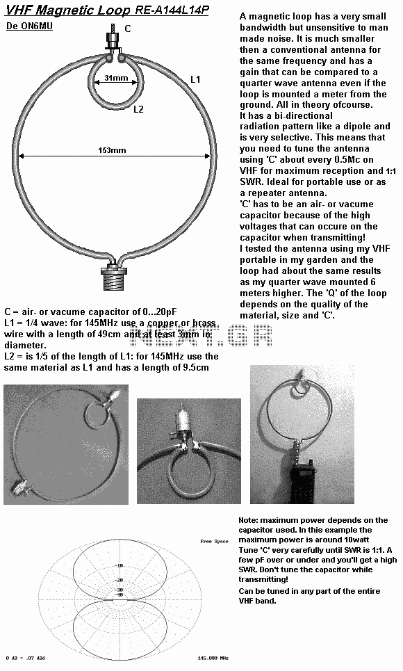
loop antennas
A loop antenna is a radio antenna made up of a loop (or loops) of wire, tubing, or other electrical conductor with its ends connected to a balanced transmission line. This design includes two distinct types of antennas: the small...
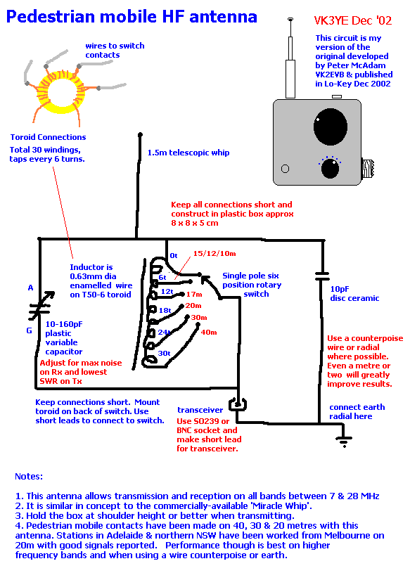
Antenna Circuits / Schematics
This document presents plans for a simple ground plane antenna that is effective in the FM band (88-108 MHz). It is constructed from a small plastic disk. The 6 x 6 loop antenna, designed by Graham Maynard, is highlighted as...
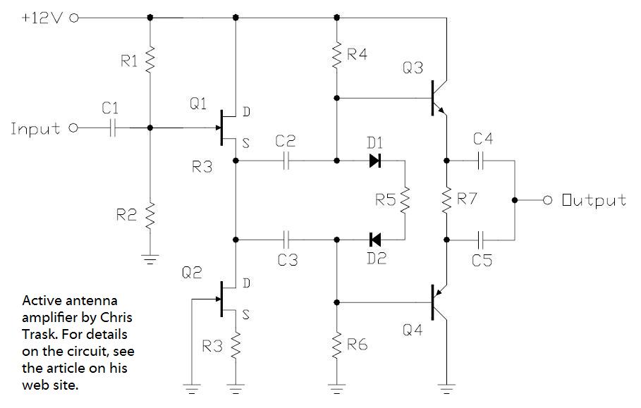
an active whip receiving antenna
In the pursuit of effective small antennas, an active whip antenna was constructed. This compact vertical antenna is linked to a preamplifier, which serves to convert the high impedance of the 50-ohm receiver and coaxial cable. Various designs exist for...
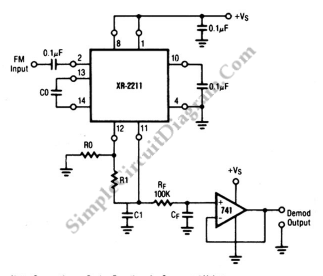
XR2211 Linear FM Detector
This is a linear frequency modulation (FM) detector circuit. This circuit is commonly utilized in telemetry applications and a wide range of analog communication systems. The primary component of this circuit...
The linear FM detector circuit is designed to demodulate frequency-modulated...
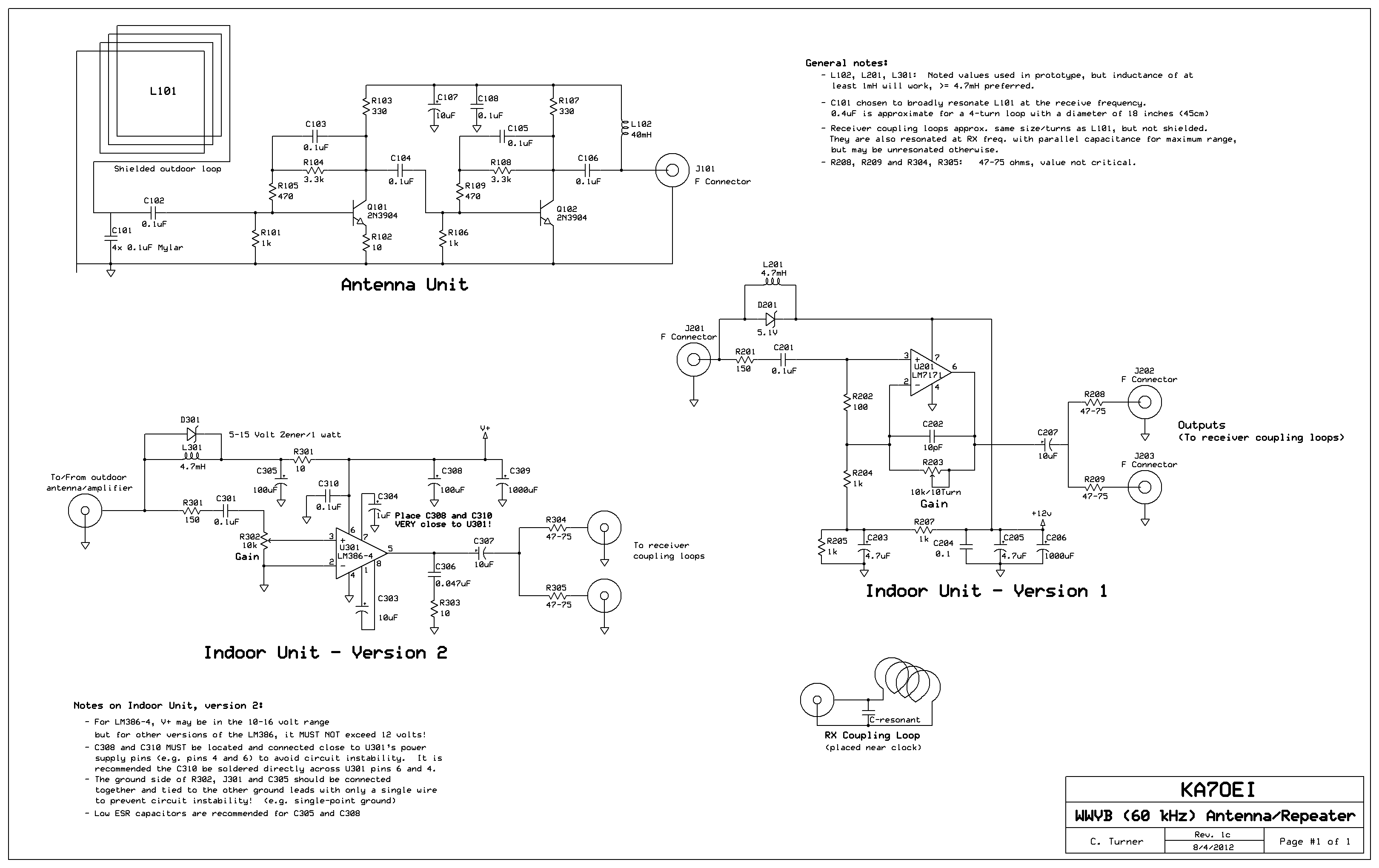
Remote antenna for 60 kHz (WWVB) reception
Inside the outdoor box where the loop is mounted, the amplifier circuitry is displayed. The four capacitors located at the lower-left corner of the perfboard are used to broadly resonate the receive loop. In the office building, which is a...
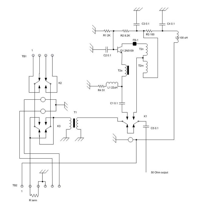
The K9AY receiving loop antenna
A K9AY antenna system and controller has been designed with the intention of creating a more effective unit at a lower cost compared to commercially available versions. The K9AY antenna features a steerable null, maintaining a gain close to unity,...
Ground pole & 2-Half-Wave Dipole Antenna
This Antenna is most widely used all over the world. For example, when you see a police car it has a transmitter with Ground Pole Antenna. The body of the car serves as ground. It accepts load from a 50-ohm...
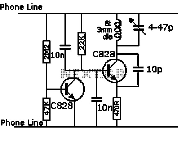
high voltage ac calibrator circuit
This is an application circuit for calibration known as a high voltage AC calibrator circuit. A key aspect of sine wave oscillator design is the stable control of amplitude. In this circuit, the amplitude is stabilized through servo control, which...
Four Foot Box Loop Antenna
Please find attached your copy of my four foot unamplified box loop. It will tune from 525 kHz to about 1710 kHz covering the entire Broadcast Band. The umbrella stand described in the article is the type you would use...