


XTR101 bridge input voltage excitation circuit diagram
#voltage reference
#bridge circuit
#LM129
#XTR101
#current source
#pressure sensor
#signal conditioning
#instrumentation amplifier
#precision measurement
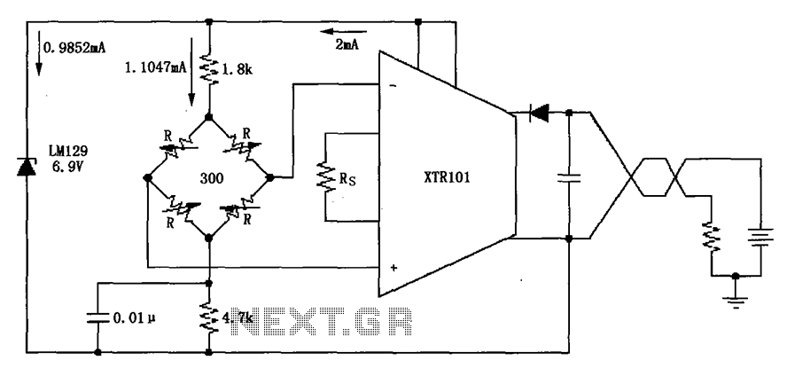
Description: The circuit utilizes the LM129 voltage regulator to produce a 6.9V voltage reference, supplying a current of 1.0147mA from the 6.9V reference voltage to the bridge. The bridge may consist of varistor-type pressure sensors.
The LM129 voltage regulator is a precision device designed for generating stable reference voltages. In this circuit, it is configured to output a nominal voltage of 6.9V, which is crucial for ensuring accurate readings from the connected sensors. The output current of 1.0147mA is specifically chosen to meet the requirements of the bridge sensor without exceeding its operational limits, thereby ensuring reliable performance.
The bridge sensor in this application is likely a varistor-type pressure sensor, which utilizes the principle of resistance change under varying pressure conditions. These sensors are known for their sensitivity and fast response times, making them suitable for applications requiring precise pressure measurements. The bridge configuration allows for differential measurements, which enhances the accuracy of the readings by canceling out common-mode noise and other interferences.
Additionally, the circuit may include passive components such as resistors and capacitors to filter noise and stabilize the voltage output. Proper layout and grounding techniques should be employed to minimize electromagnetic interference (EMI), which can affect the performance of the voltage reference and the sensor readings.
In summary, the integration of the LM129 voltage regulator with a varistor-type bridge sensor in this circuit provides a robust solution for generating a stable voltage reference and accurate pressure measurements, essential for various applications in electronics and instrumentation. As shown, the circuit uses the LM129 regulator to generate 6.9V voltage reference, provided 1.0147mA current from 6.9V reference voltage to the bridge. Bridge may be as pressur e sensors varistor-type bridge sensor.
The LM129 voltage regulator is a precision device designed for generating stable reference voltages. In this circuit, it is configured to output a nominal voltage of 6.9V, which is crucial for ensuring accurate readings from the connected sensors. The output current of 1.0147mA is specifically chosen to meet the requirements of the bridge sensor without exceeding its operational limits, thereby ensuring reliable performance.
The bridge sensor in this application is likely a varistor-type pressure sensor, which utilizes the principle of resistance change under varying pressure conditions. These sensors are known for their sensitivity and fast response times, making them suitable for applications requiring precise pressure measurements. The bridge configuration allows for differential measurements, which enhances the accuracy of the readings by canceling out common-mode noise and other interferences.
Additionally, the circuit may include passive components such as resistors and capacitors to filter noise and stabilize the voltage output. Proper layout and grounding techniques should be employed to minimize electromagnetic interference (EMI), which can affect the performance of the voltage reference and the sensor readings.
In summary, the integration of the LM129 voltage regulator with a varistor-type bridge sensor in this circuit provides a robust solution for generating a stable voltage reference and accurate pressure measurements, essential for various applications in electronics and instrumentation. As shown, the circuit uses the LM129 regulator to generate 6.9V voltage reference, provided 1.0147mA current from 6.9V reference voltage to the bridge. Bridge may be as pressur e sensors varistor-type bridge sensor.
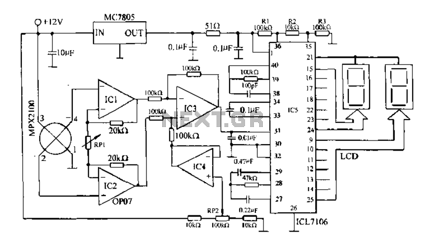
Digital pressure measuring circuit
Digital pressure measuring circuit using AD7710/7715/7730 multifunction digital sensor signal conditioning ICs. These ICs integrate a digital interface with the control port, a clock generator, a digital filter, amplitude modulation, a programmable gain amplifier, an A/D converter, and other electronic...

Pressure Switch Design With Semiconductor Pressure Sensors
Today's electronic designs focus on optimizing efficiency to minimize unnecessary power dissipation, aiming to maximize battery life in portable applications and ensure that devices operate as cool as possible. One of the challenges facing designers of synchronous buck PWM controllers...
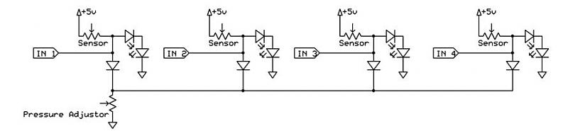
pressure sensor circuit
A dance pad consists of four pressure sensors (up, down, left, right). A USB controller has already been created for the dance pad, and the next step involves connecting the actual sensors. The intention is to pull the input down...
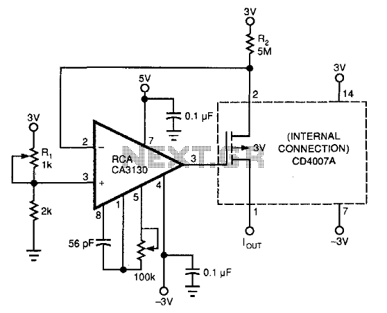
Current Source
This circuit utilizes commonly available components to create a 0-to-200-nA current source. It incorporates a PMOS transistor from the input stage of a DC4007A, which is more accessible than a standalone PMOS transistor. The CA3130 operational amplifier functions as a...
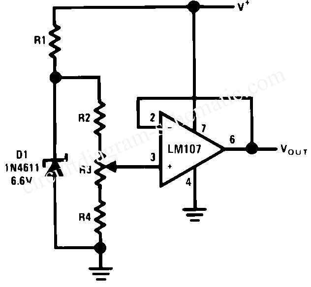
Positive Voltage Reference Circuit
The circuit is designed for high precision operation over an extended temperature range, provided that V+ remains relatively constant, as the current IZ is dependent on V+. Resistors R1, R2, R3, and R4 are selected to ensure the appropriate IZ...

Signal Conditioning Analog Front-end for Microcontrollers
The I/O board incorporates 16-bit resolution voltage analog inputs and outputs, along with a 4-20mA current loop transmitter and receiver for microcontroller applications. The document discusses amplifier circuits and schematics, including a signal conditioning variable gain amplifier, analog filter, and...
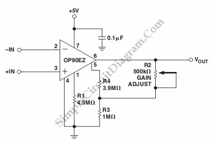
Micropower Single-Supply Instrumentation Amplifier
A schematic diagram of a micropower single-supply instrumentation amplifier circuit is presented. This circuit requires only 15µA of current and can provide over...
The micropower single-supply instrumentation amplifier circuit is designed for applications where low power consumption is critical. The amplifier...
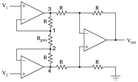
The instrumentation amplifier
It is advantageous to adjust the gain of an amplifier circuit without modifying more than one resistor value, unlike the previous design of the differential amplifier. The instrumentation amplifier builds upon the last version of the differential amplifier to provide...
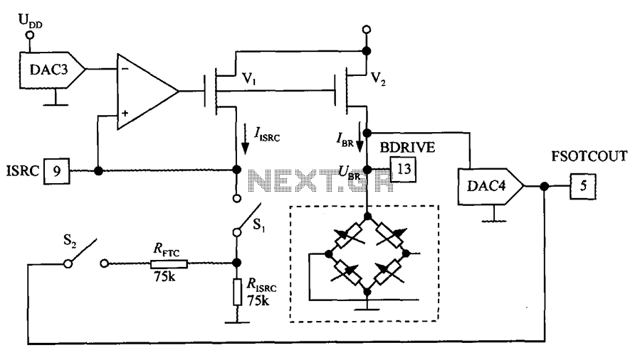
Bridge the digital pressure signal conditioner MAX1458 excitation circuit diagram
The excitation circuit for the digital pressure signal conditioner MAX1458 is illustrated. The output DAC3 is utilized to adjust the sensor excitation current (IBR), enabling full-scale fine calibration. The reference current (IISRC) is determined by the resistor RISRC and the...