


XTR108 voltage excitation bridge circuit diagram
#voltage excitation
#bridge circuit
#XTR108
#linearization
#RTD
#sensor
#signal conditioning
#instrumentation amplifier
#precision measurement
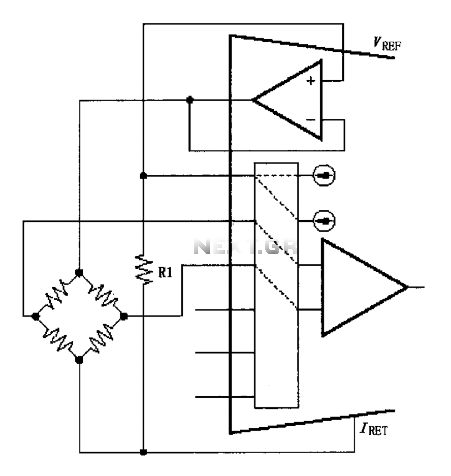
Description: The circuit for the bridge excitation voltage XTR108 is linearized using adjusted algorithms that correspond to the linearization of the RTD response. The excitation voltage VEX is defined as 2IREFR1, where VEX represents the excitation voltage applied at both ends of the bridge.
The XTR108 is a precision current loop transmitter designed for use in applications that require the measurement of resistance temperature detectors (RTDs). In this context, the bridge circuit is a critical component that allows for the accurate measurement of temperature by converting the resistance changes of the RTD into a corresponding voltage signal.
The excitation voltage (VEX) provided to the bridge is crucial for maintaining linearity in the output. The relationship VEX = 2IREFR1 indicates that the excitation voltage is twice the product of the reference current (IREF) and the resistance (R1) used in the circuit. This configuration helps to ensure that the output voltage remains proportional to the temperature changes detected by the RTD.
The linearization algorithms applied in this circuit are essential for correcting any non-linearities that may arise from the RTD's response characteristics. By adjusting the excitation voltage and employing these algorithms, the system can achieve a more accurate and stable output, which is particularly important in precision temperature measurement applications.
In summary, the XTR108 bridge circuit effectively utilizes a linearized approach to provide a stable excitation voltage, ensuring that the RTD's resistance changes correspond accurately to temperature variations. This method enhances the reliability and precision of temperature readings in various industrial and scientific applications. As shown for the bridge circuit excitation voltage XTR108. Circuit for the bridge excitation voltage is linearized adjusted, linearized algorithms that RTD linearization same r esponse. Excitation voltage VEX 2IREFR1, where VEX is the excitation voltage at both ends of the bridge.
The XTR108 is a precision current loop transmitter designed for use in applications that require the measurement of resistance temperature detectors (RTDs). In this context, the bridge circuit is a critical component that allows for the accurate measurement of temperature by converting the resistance changes of the RTD into a corresponding voltage signal.
The excitation voltage (VEX) provided to the bridge is crucial for maintaining linearity in the output. The relationship VEX = 2IREFR1 indicates that the excitation voltage is twice the product of the reference current (IREF) and the resistance (R1) used in the circuit. This configuration helps to ensure that the output voltage remains proportional to the temperature changes detected by the RTD.
The linearization algorithms applied in this circuit are essential for correcting any non-linearities that may arise from the RTD's response characteristics. By adjusting the excitation voltage and employing these algorithms, the system can achieve a more accurate and stable output, which is particularly important in precision temperature measurement applications.
In summary, the XTR108 bridge circuit effectively utilizes a linearized approach to provide a stable excitation voltage, ensuring that the RTD's resistance changes correspond accurately to temperature variations. This method enhances the reliability and precision of temperature readings in various industrial and scientific applications. As shown for the bridge circuit excitation voltage XTR108. Circuit for the bridge excitation voltage is linearized adjusted, linearized algorithms that RTD linearization same r esponse. Excitation voltage VEX 2IREFR1, where VEX is the excitation voltage at both ends of the bridge.
RTD thermometer
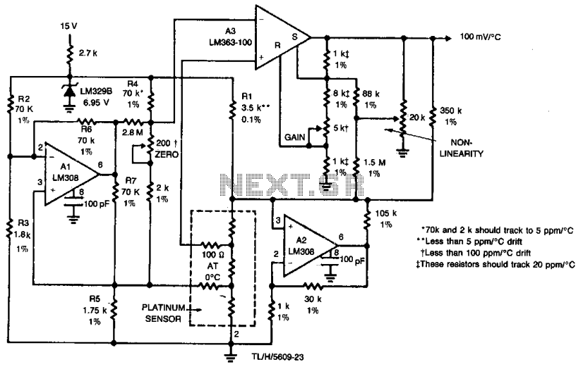
This thermometer achieves an accuracy of 0.01°C across a temperature range of -50°C to +150°C. A distinctive trimming arrangement eliminates complex interactions during the trimming process, allowing for simultaneous adjustments of zero gain and nonlinearity correction. Additional operational amplifiers facilitate...
a simple electrocardiogram board
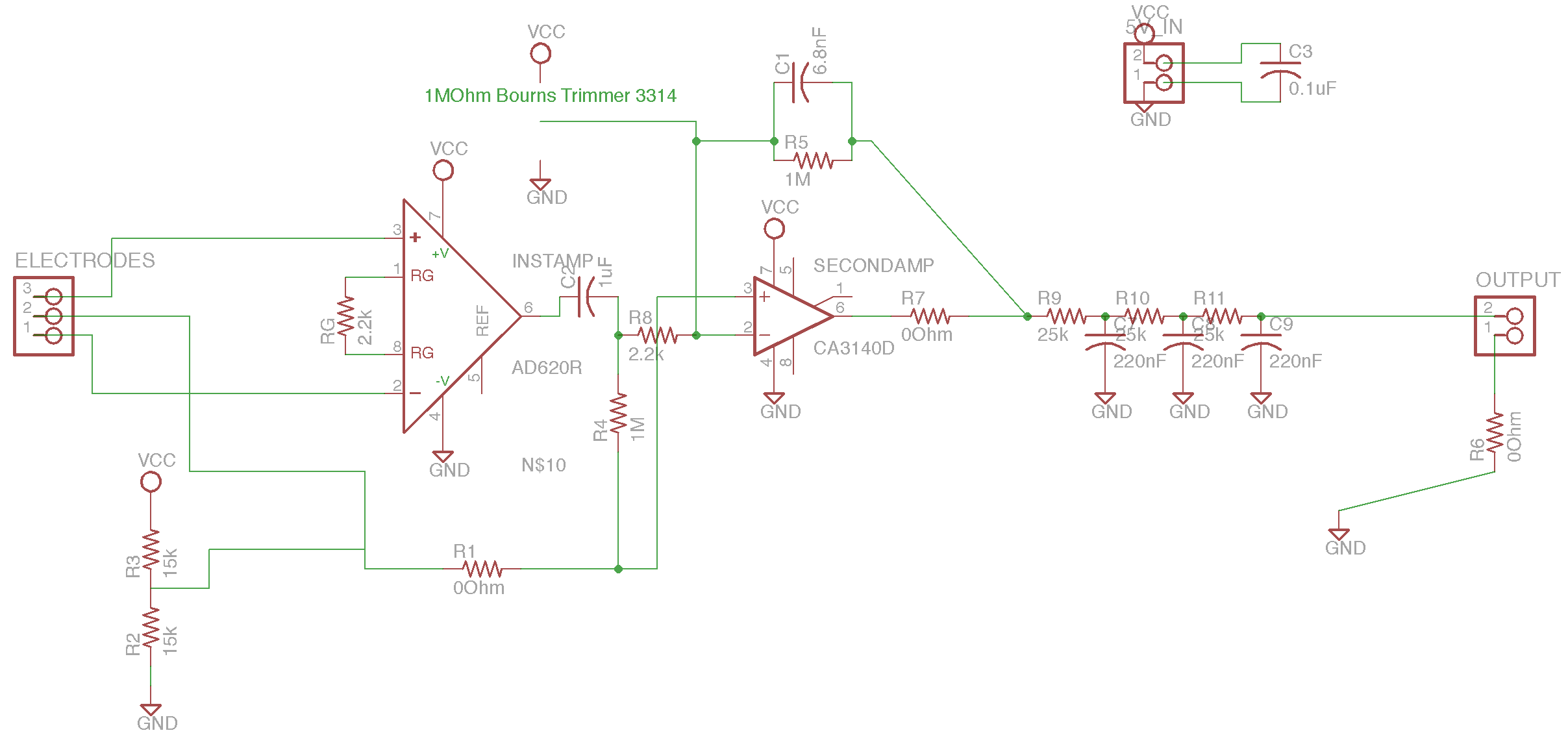
The circuit is based on the designs of Chipstein and Cornell, utilizing an instrumentation amplifier (AD620) to measure the voltage difference between two locations on the body. A second amplifier (CA3140) further amplifies this differential signal. A potentiometer is employed...
Signal Conditioners Information
Signal conditioning involves a series of operations applied to a signal to make it compatible for interfacing with other devices or systems. Signal conditioners are the devices that execute this operation, featuring both an input and an output. Typically, the...

Signal Conditioning Analog Front-end for Microcontrollers
The I/O board incorporates 16-bit resolution voltage analog inputs and outputs, along with a 4-20mA current loop transmitter and receiver for microcontroller applications. The document discusses amplifier circuits and schematics, including a signal conditioning variable gain amplifier, analog filter, and...
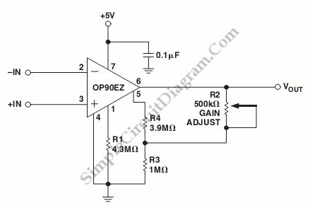
Micropower Single-Supply Instrumentation Amplifier
A schematic diagram of a micropower single-supply instrumentation amplifier circuit is presented. This circuit requires only 15µA of current and can provide over...
The micropower single-supply instrumentation amplifier circuit is designed for applications where low power consumption is critical. The amplifier...
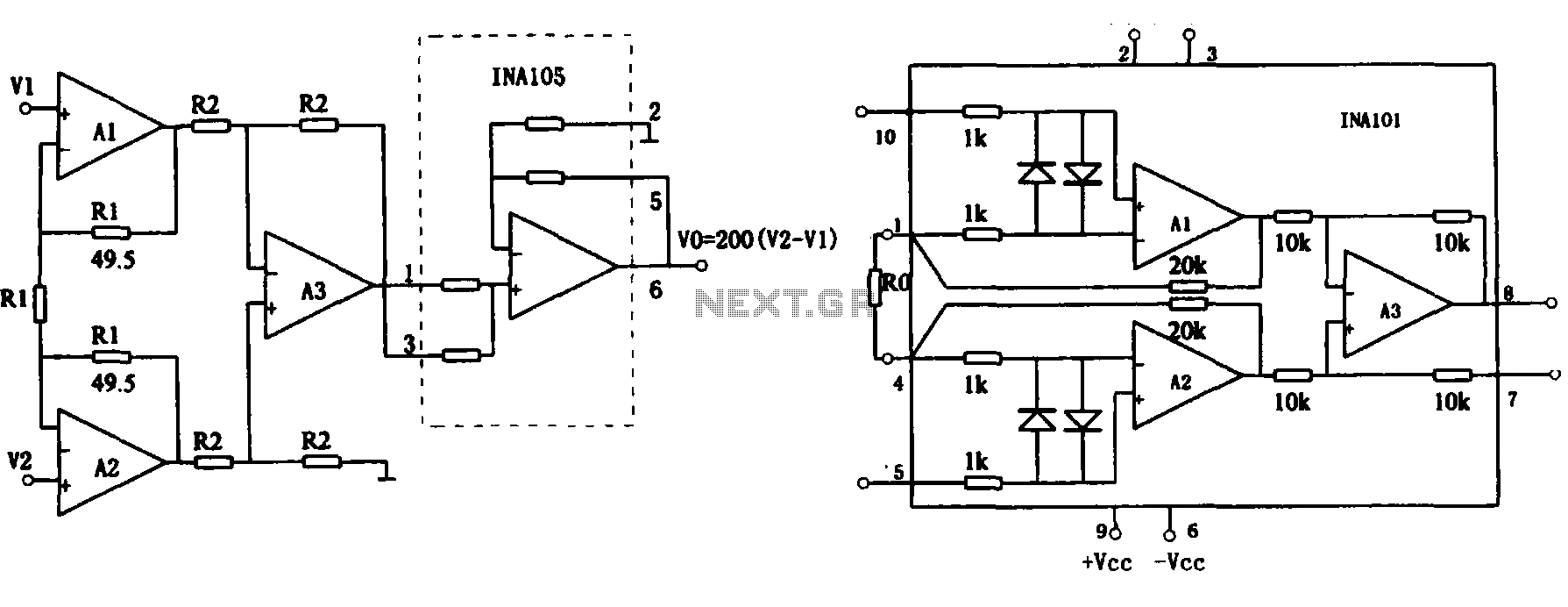
Extended common mode range of the instrumentation amplifier (INA101) circuit
This document describes the extended common mode input voltage range of an instrument amplifier circuit. The circuit consists of three precision instrument amplifiers, A1, A2, and A3, which can be INA101 or INA102 models. The figure illustrates that A1, A2,...
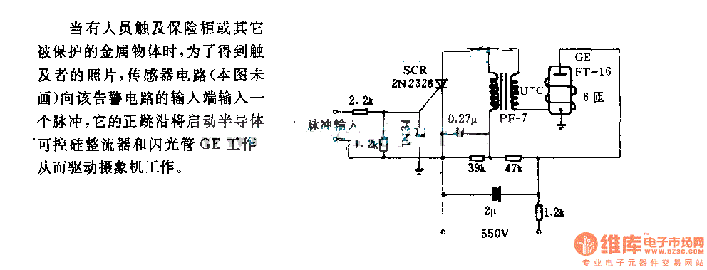
The alarm circuit diagram for safety box and other metal objects
When an individual touches the safety box or other protected metal objects, the sensor circuit generates a pulse to the alarm circuit. The positive edge of this pulse activates the semiconductor and thyristor flash GE, subsequently triggering the camera to...
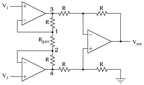
The instrumentation amplifier
It is advantageous to adjust the gain of an amplifier circuit without modifying more than one resistor value, unlike the previous design of the differential amplifier. The instrumentation amplifier builds upon the last version of the differential amplifier to provide...
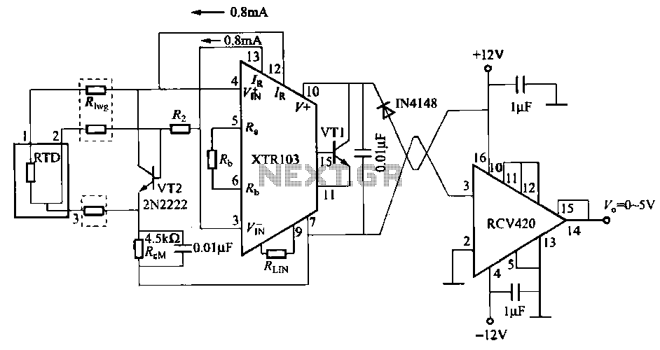
RTD remote temperature sensing current voltage conversion circuit
When the RTD temperature sensor is positioned far from the amplifier, the resistance of the sensor leads and their susceptibility to interference and other issues cannot be overlooked. The circuit shown in the figure addresses this problem. It utilizes a...