


BFO metal Detector Circuit with IC 4093
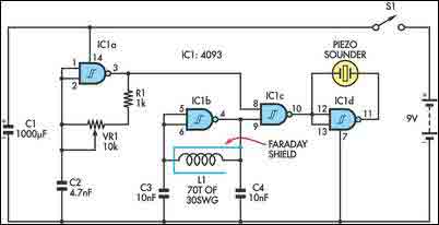
Description: The circuit incorporates two oscillators, both operating at about 40kHz. The first, IC1a, is a standard CMOS oscillator with its frequency adjustable via VR1. The frequency of the second, IC1b, is highly dependent on the inductance of coil L1, so that its frequency shifts in the presence of metal. L1 is 70 turns of 0.315mm enamelled copper wire wound on a 120mm diameter former. More: The two oscillator signals are mixed through IC1c, to create a beat note. IC1d and IC1c drive the piezo sounder in push-pull fashion, thereby boosting the output. Unlike many other metal locators of its kind, this locator is particularly easy to tune. Around the midpoint setting of VR1, there will be a loud beat frequency with a null point in the middle. The locator needs to be tuned to a low frequency beat note to one or the other side of this null point. Depending on which side is chosen, it will be sensitive to either ferrous or non-ferrous metals. Besides detecting objects under the ground, the circuit could serve well as a pipe locator.
The circuit design features two oscillators, designated as IC1a and IC1b, both operating at an approximate frequency of 40 kHz. IC1a functions as a standard CMOS oscillator, with its frequency being adjustable through a variable resistor, VR1. This adjustability allows for fine-tuning of the oscillation frequency, which is crucial for optimal performance in metal detection applications. The second oscillator, IC1b, operates with a frequency that is influenced by the inductance of an inductor, L1. This inductor is constructed from 70 turns of 0.315 mm enamelled copper wire, wound around a former with a diameter of 120 mm. The inductance of L1 is sensitive to nearby metallic objects, causing a shift in the oscillation frequency of IC1b when such objects are detected.
The outputs from both oscillators are combined using IC1c, which serves as a mixer to generate a beat frequency. This beat frequency is essential for the operation of the circuit, as it provides an audible signal that indicates the presence of metal. The piezo sounder is driven in a push-pull configuration by the outputs of IC1c and IC1d, which enhances the sound output, making the detection signal more pronounced.
Tuning the circuit is simplified due to its design, allowing the user to adjust VR1 to find a loud beat frequency at a midpoint setting. This midpoint also defines a null point, where the output signal is minimized. The user can adjust the circuit to either side of this null point, enabling sensitivity to specific types of metals—either ferrous or non-ferrous. This flexibility makes the circuit not only effective for detecting buried metallic objects but also suitable for locating underground pipes. The design's adaptability and ease of tuning contribute to its effectiveness in various metal detection scenarios.The circuit incorporates two oscillators, both operating at about 40kHz. The first, IC1a, is a standard CMOS oscillator with its frequency adjustable via VR1. The frequency of the second, IC1b, is highly dependent on the inductance of coil L1, so that its frequency shifts in the presence of metal. L1 is 70 turns of 0.315mm enamelled copper wire wound on a 120mm diameter former. The two oscillator signals are mixed through IC1c, to create a beat note. IC1d and IC1c drive the piezo sounder in push-pull fashion, thereby boosting the output. Unlike many other metal locators of its kind, this locator is particularly easy to tune. Around the midpoint setting of VR1, there will be a loud beat frequency with a null point in the middle. The locator needs to be tuned to a low frequency beat note to one or the other side of this null point.
Depending on which side is chosen, it will be sensitive to either ferrous or non-ferrous metals. Besides detecting objects under the ground, the circuit could serve well as a pipe locator.
The circuit design features two oscillators, designated as IC1a and IC1b, both operating at an approximate frequency of 40 kHz. IC1a functions as a standard CMOS oscillator, with its frequency being adjustable through a variable resistor, VR1. This adjustability allows for fine-tuning of the oscillation frequency, which is crucial for optimal performance in metal detection applications. The second oscillator, IC1b, operates with a frequency that is influenced by the inductance of an inductor, L1. This inductor is constructed from 70 turns of 0.315 mm enamelled copper wire, wound around a former with a diameter of 120 mm. The inductance of L1 is sensitive to nearby metallic objects, causing a shift in the oscillation frequency of IC1b when such objects are detected.
The outputs from both oscillators are combined using IC1c, which serves as a mixer to generate a beat frequency. This beat frequency is essential for the operation of the circuit, as it provides an audible signal that indicates the presence of metal. The piezo sounder is driven in a push-pull configuration by the outputs of IC1c and IC1d, which enhances the sound output, making the detection signal more pronounced.
Tuning the circuit is simplified due to its design, allowing the user to adjust VR1 to find a loud beat frequency at a midpoint setting. This midpoint also defines a null point, where the output signal is minimized. The user can adjust the circuit to either side of this null point, enabling sensitivity to specific types of metals—either ferrous or non-ferrous. This flexibility makes the circuit not only effective for detecting buried metallic objects but also suitable for locating underground pipes. The design's adaptability and ease of tuning contribute to its effectiveness in various metal detection scenarios.The circuit incorporates two oscillators, both operating at about 40kHz. The first, IC1a, is a standard CMOS oscillator with its frequency adjustable via VR1. The frequency of the second, IC1b, is highly dependent on the inductance of coil L1, so that its frequency shifts in the presence of metal. L1 is 70 turns of 0.315mm enamelled copper wire wound on a 120mm diameter former. The two oscillator signals are mixed through IC1c, to create a beat note. IC1d and IC1c drive the piezo sounder in push-pull fashion, thereby boosting the output. Unlike many other metal locators of its kind, this locator is particularly easy to tune. Around the midpoint setting of VR1, there will be a loud beat frequency with a null point in the middle. The locator needs to be tuned to a low frequency beat note to one or the other side of this null point.
Depending on which side is chosen, it will be sensitive to either ferrous or non-ferrous metals. Besides detecting objects under the ground, the circuit could serve well as a pipe locator.

CD4047 CMOS OSCILLATOR
This CMOS square-wave oscillator utilizes the 4047 multivibrator circuit, suitable for both monostable (one-shot) and astable applications. In the provided configuration, the 4047 operates as an astable multivibrator. The circuit features three outputs from the 4047, with the first being...

Measuring Inductors
Often, there are instances where it becomes necessary to wind a coil for a project or to identify an unmarked coil found in a collection. To determine its inductance, an oscilloscope can be utilized. A resonant circuit can be constructed...
why doesnt this circuit oscillate
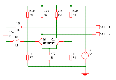
The buba oscillator initially failed to oscillate. The first step is to check the fundamental components, as minor errors in the values of capacitors, resistors, and inductors can significantly impact performance. It is advisable to measure component values with a...

Oscillator-clock-generator
This self-starting fixed-frequency oscillator circuit provides excellent frequency stability. R1 and C1 form the frequency-determining network, while R2 delivers the regenerative feedback. Diode D1 improves stability by compensating for the difference between VaH and VsurrLY. In applications where a precision...
Single Zone CMOS Alarm
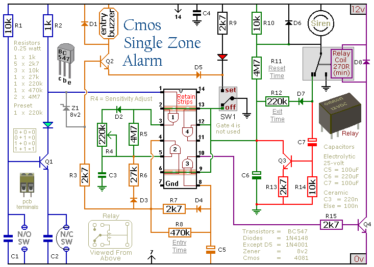
This circuit features automatic Exit/Entry delays, timed Bell Cut-off and System Reset. It has provision for normally open and normally closed switches and will accommodate the usual input devices such as Foil Tape, Pressure Mats, Magnetic Reed Contacts, Passive Infrared...
Metal detector circuit diagram 5
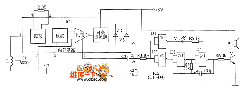
The metal detector circuit comprises an oscillator and a sound-light alarm circuit. The oscillator circuit includes an inductor (L), a capacitor (C1), a sensor switch integrated circuit (IC1) that integrates the oscillator, detector, comparator circuit, and peripheral components. The sound-light...

Wide frequency oscillator
An oscillator/amplifier is resistively tunable over a wide frequency range. Feedback circuits containing operational amplifiers, resistors, and capacitors synthesize the electrical effects of inductance and capacitance in parallel between the input terminals. The synthetic inductance and capacitance, and therefore the...

Automatic Dual Output Display
This circuit sequentially lights ten bulbs, first in one direction and then in the opposite direction, creating an appealing visual effect. Gates N1 and N2 form an oscillator, which serves as a clock for the BCD up/down counter CD4510 (IC2)....

HEE HAW ELECTRONIC SIREN
The oscillator based on IC2 generates sound, with its output linked to the base of TR1, which amplifies the signal to drive the speaker. Resistor R4 is included to limit the current through TR1 to a safe level. The oscillation...