


Low Cost Metal Detector Circuit PCB
#BC548
#AM radio
#DIY
#hobby circuit
#oscillator
#low cost
#PCB
#metal detection
#simple circuit
#transistor
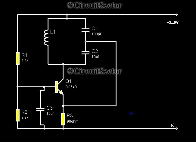
Description: Metal detectors are typically complex devices that often incorporate expensive components, making DIY metal detector circuits uncommon. However, this metal detector hobby circuit can be built using only a few components, such as a BC548 transistor and a standard AM radio. The schematic for this metal detector operates in accordance with the frequency of any tuned AM radio. Upon powering the circuit, the radio will initially remain silent because the oscillation from the radio and the metal detector's oscillator will be in sync, causing them to cancel each other out. It is essential to adjust the frequency of the metal detector circuit to match the tuned frequency of the radio. When a metal object comes near the circuit, the cancellation of the two signals ceases, resulting in the radio producing sound.
The metal detector circuit utilizes a BC548 transistor, which serves as the primary active component. This transistor is configured in a common-emitter arrangement, allowing it to amplify the signal generated by the oscillator. The circuit also includes a few passive components, such as resistors and capacitors, which are crucial for setting the oscillation frequency. The AM radio acts as a receiver for the oscillation signal, which is modulated by the presence of metal objects.
When constructing this circuit, the first step involves connecting the BC548 transistor in a way that it can generate oscillations. The base of the transistor is connected to a resistor that sets the biasing point, ensuring the transistor operates in the active region. The collector is linked to a tuned circuit, which consists of an inductor and a capacitor, forming a resonant circuit that determines the oscillation frequency.
The output from the collector is fed into the AM radio's input. Initially, when the circuit is powered, both the radio and the metal detector oscillator produce signals at the same frequency, leading to destructive interference and silence in the radio. To ensure proper operation, the frequency of the metal detector's oscillator must be fine-tuned to match the AM radio's tuned frequency.
When a metal object enters the detection zone, it alters the oscillation conditions of the circuit, disrupting the cancellation effect. This results in a change in the output signal, which the AM radio can detect, leading to the production of sound. The sensitivity of the metal detector can be adjusted by modifying the values of the passive components, allowing for detection of various types of metal objects at different distances.
This simple yet effective design demonstrates how basic electronic components can be utilized to create a functional metal detector, making it an excellent project for hobbyists and those interested in electronics.Metal detectors are usually very complicated and it may be consist of very costly components and metal detector DIY circuits are rare. However this metal detector hobby circuit can be constructed by only a few components such as BC548 and an ordinary AM radio that we usually use.
This metal detector schematic shown in the figure oscillates accordi ng to the frequency of any tuned AM radio. When the circuit powers up, the radio will not produce any sound because the radio oscillatory and the the metal detector oscillator will be in the same frequency and each will cancel itself. We all need to adjust the frequency of electronics circuit of metal detector to the tuned radio frequency.
Whenever a metal part come aside the circuit, the cancellation of two signals stops and the radio starts producing sound.
The metal detector circuit utilizes a BC548 transistor, which serves as the primary active component. This transistor is configured in a common-emitter arrangement, allowing it to amplify the signal generated by the oscillator. The circuit also includes a few passive components, such as resistors and capacitors, which are crucial for setting the oscillation frequency. The AM radio acts as a receiver for the oscillation signal, which is modulated by the presence of metal objects.
When constructing this circuit, the first step involves connecting the BC548 transistor in a way that it can generate oscillations. The base of the transistor is connected to a resistor that sets the biasing point, ensuring the transistor operates in the active region. The collector is linked to a tuned circuit, which consists of an inductor and a capacitor, forming a resonant circuit that determines the oscillation frequency.
The output from the collector is fed into the AM radio's input. Initially, when the circuit is powered, both the radio and the metal detector oscillator produce signals at the same frequency, leading to destructive interference and silence in the radio. To ensure proper operation, the frequency of the metal detector's oscillator must be fine-tuned to match the AM radio's tuned frequency.
When a metal object enters the detection zone, it alters the oscillation conditions of the circuit, disrupting the cancellation effect. This results in a change in the output signal, which the AM radio can detect, leading to the production of sound. The sensitivity of the metal detector can be adjusted by modifying the values of the passive components, allowing for detection of various types of metal objects at different distances.
This simple yet effective design demonstrates how basic electronic components can be utilized to create a functional metal detector, making it an excellent project for hobbyists and those interested in electronics.Metal detectors are usually very complicated and it may be consist of very costly components and metal detector DIY circuits are rare. However this metal detector hobby circuit can be constructed by only a few components such as BC548 and an ordinary AM radio that we usually use.
This metal detector schematic shown in the figure oscillates accordi ng to the frequency of any tuned AM radio. When the circuit powers up, the radio will not produce any sound because the radio oscillatory and the the metal detector oscillator will be in the same frequency and each will cancel itself. We all need to adjust the frequency of electronics circuit of metal detector to the tuned radio frequency.
Whenever a metal part come aside the circuit, the cancellation of two signals stops and the radio starts producing sound.
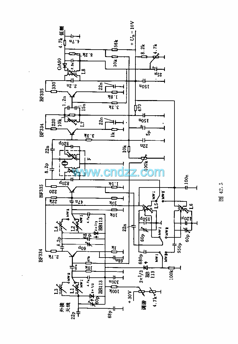
Automobile AM radio circuit
This circuit illustrates the high and mid-frequency sections of a car radio. The medium wave band I operates within the frequency range of 520 to 950 kHz, while Poland II operates between 900 and 1640 kHz. The circuit employs loop...
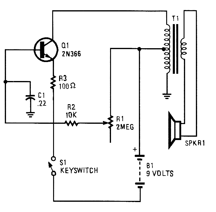
SINGLE TRANSISTOR CODE PRACTICE OSCILLATOR
A 2N366 is configured as an audio feedback oscillator using an audio transformer. Adjust R1 for proper operation and the desired audio note.
The circuit utilizes a 2N366 transistor, which is a general-purpose NPN transistor, serving as the primary active component...
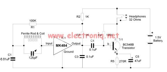
mk484 am radio circuit design project
The MK484 AM radio circuit offers a comprehensive solution featuring an RF amplifier, detection, and an automatic gain control (AGC) circuit. It requires only a few external components to achieve high-quality AM tuning. The circuit has an input impedance of...
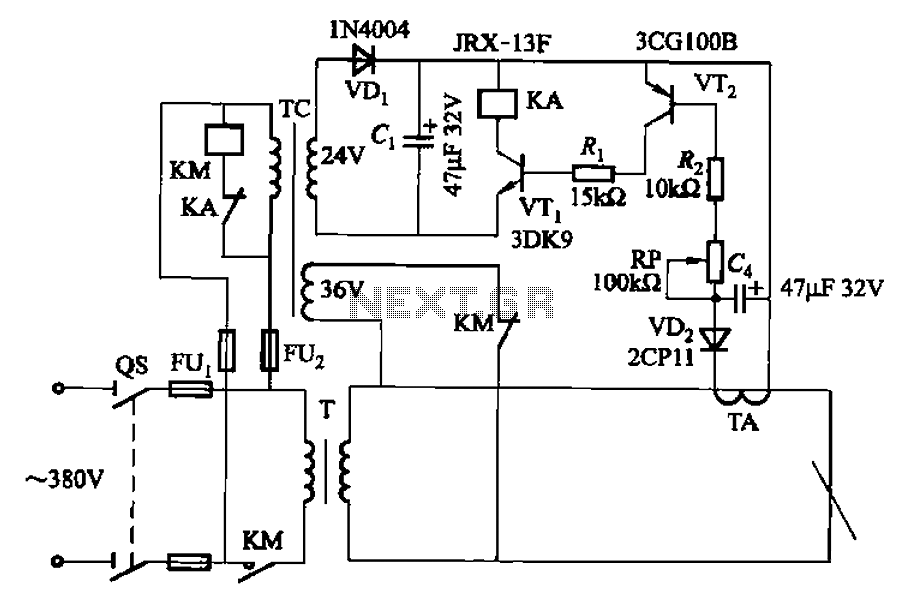
AC arc welding machine transistor load power path from 2
The AC arc welding machine's transistor load path for the power from the second circuit is illustrated. The figure shows a current transformer with a core cross-section of 25 mm². The transformer has a primary winding with a certain number...
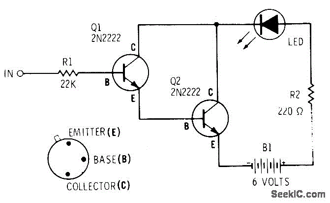
DARLINGTON LOGIC PROBE
A two-transistor Darlington connection offers a very high input impedance, ensuring that it does not load the logic circuit being monitored. This configuration drives an LED that illuminates when a logic high (1) is present at the input.
The two-transistor Darlington...
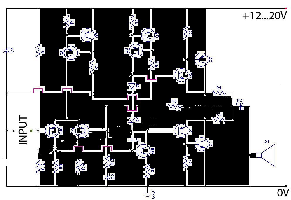
AB Transistor Audio Power Amplifier
This is a Class AB transistor power amplifier. It is straightforward to construct, utilizing standard components, and is known for its stability and reliability. The entire circuit employs commonly available parts and can be easily assembled on a general-purpose board....
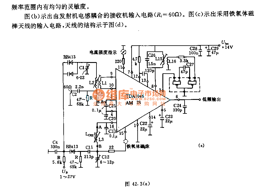
IC AM radio circuit
The receiver input circuit is powered by a 60Ω generator. A low-pass filter is employed to permit the entire frequency range while maintaining uniform sensitivity. The receiver input circuit is coupled with a transmitter inductive component (Ri = 60Ω). Additionally,...
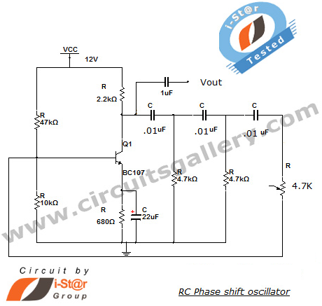
RC Phase Shift Oscillator Using Transistor (BJT): Circuit & Working
This section introduces a transistor oscillator circuit known as the RC Phase Shift Oscillator. An oscillator is an electronic circuit that functions as a sine wave generator, requiring only a DC power supply. It is commonly used in variable frequency...
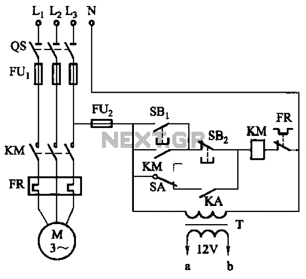
Six a start and stop intermittent cycle control circuits
The circuit illustrated in Figure 3-81 employs a transistor delay circuit to facilitate start-stop cycle control. It can operate in both manual and automatic modes. The circuit is primarily governed by the motor run time circuit, which includes transistors VTi...